
Methods and apparatus for concealing sensors and other components of electronic devices

a technology of electronic devices and sensors, applied in the field of methods and apparatus for concealing sensors and other components of electronic devices, can solve the problems of impeded light passage from the outside of the device, reflected back outwards,

Active Publication Date: 2012-09-27
APPLE INC
View PDF5 Cites 42 Cited by
  • Summary
  • Abstract
  • Description
  • Claims
  • Application Information

AI Technical Summary

Benefits of technology

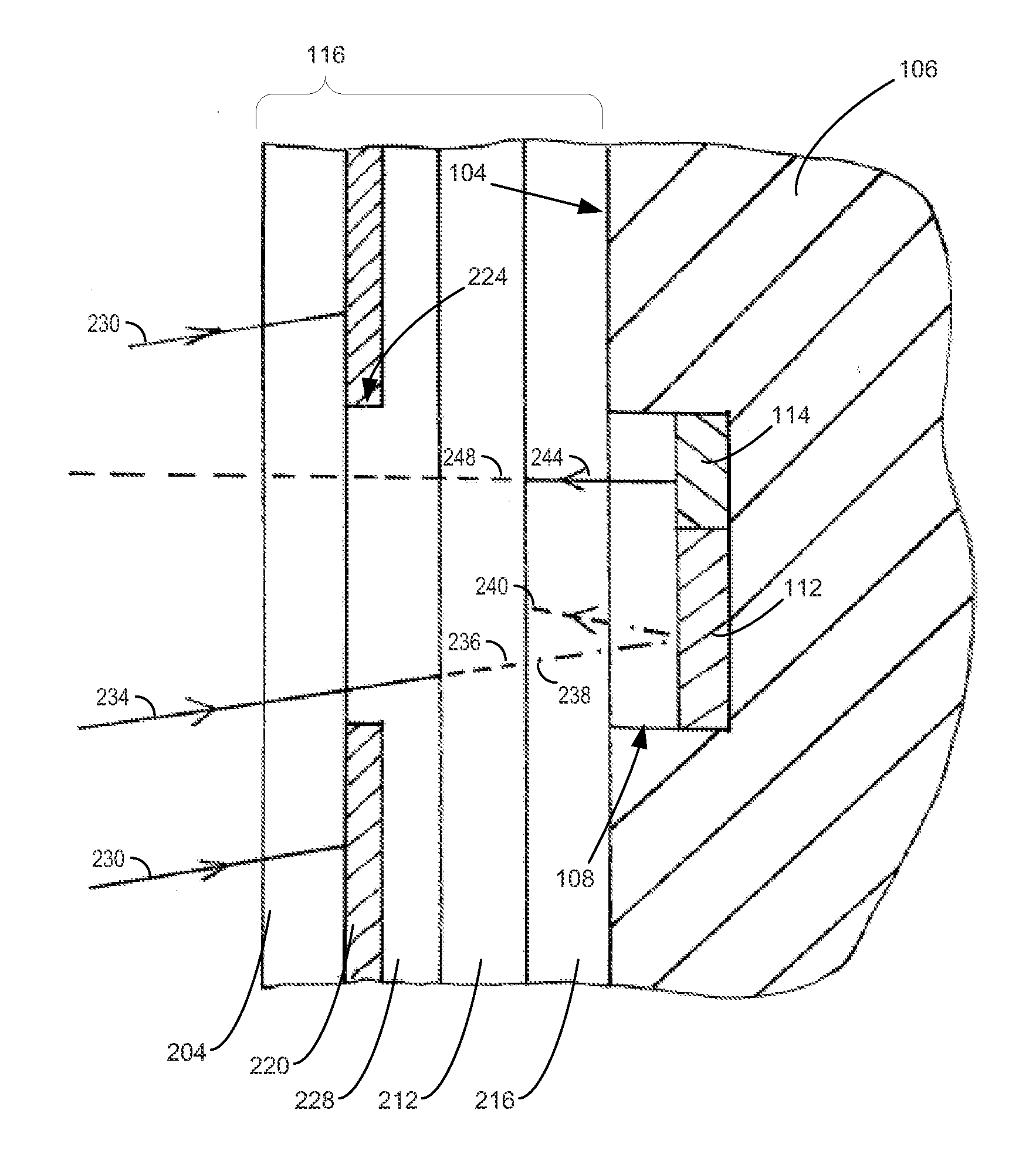
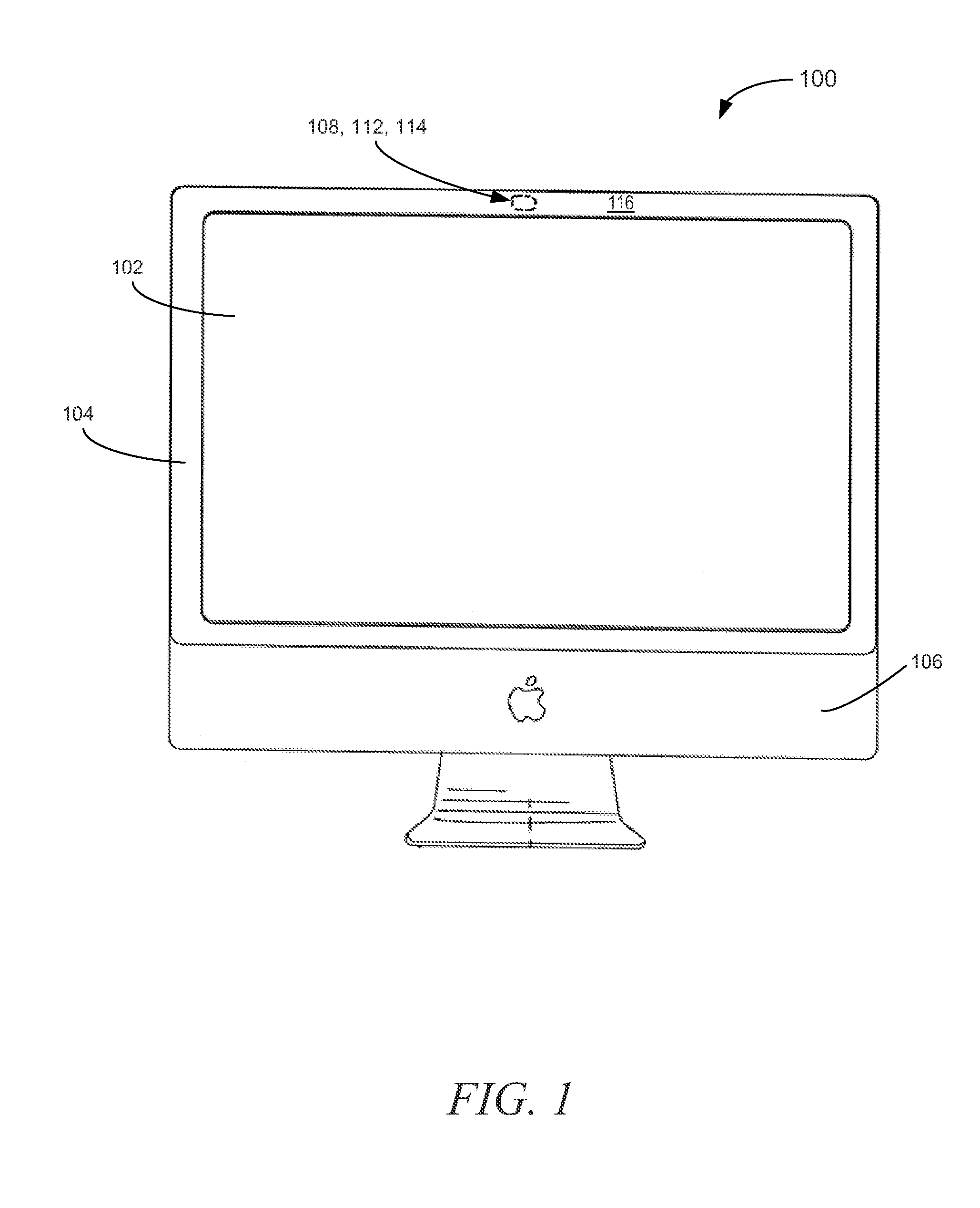
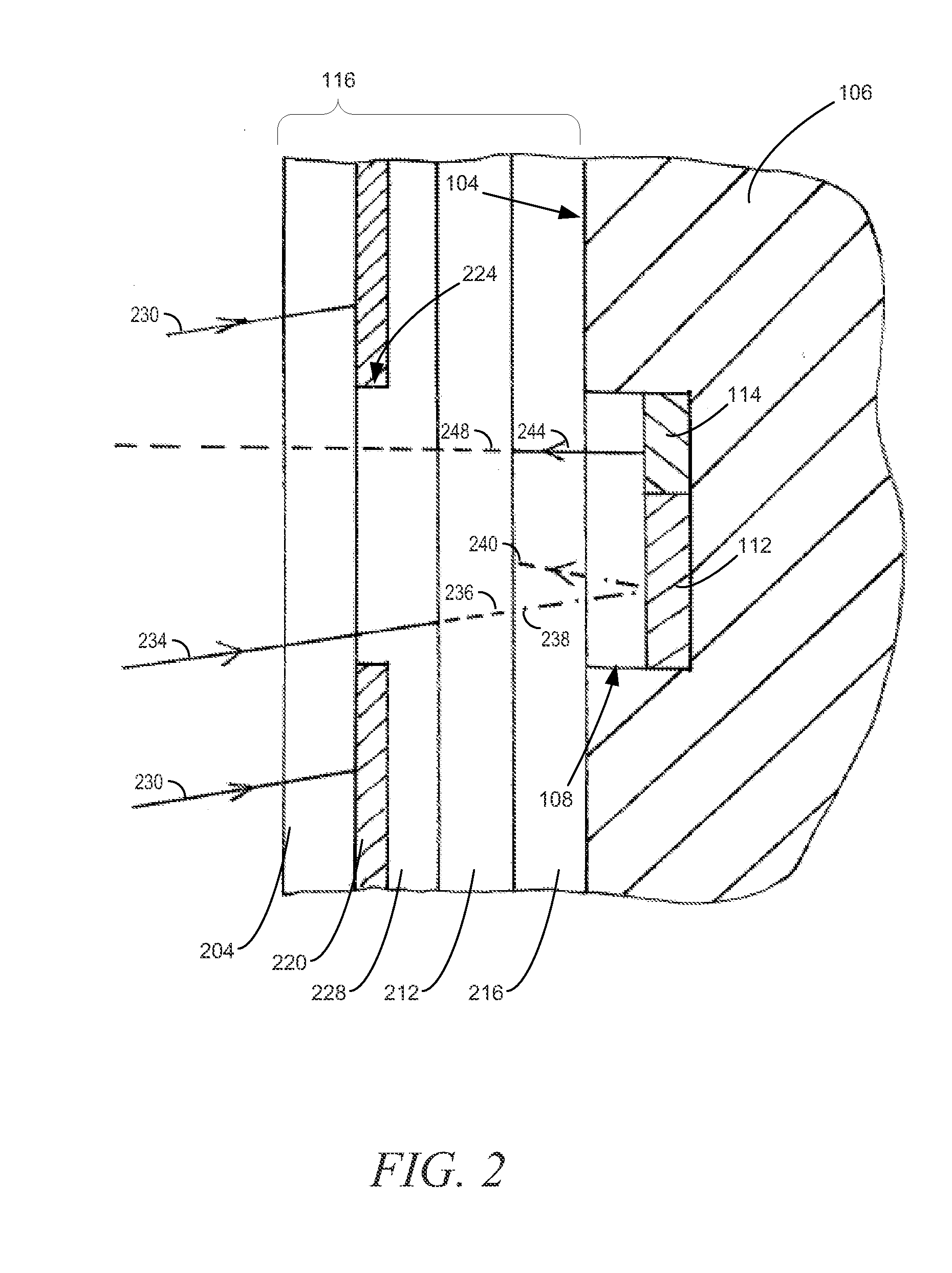
[0003]The present invention provides a concealing structure to at least partially conceal a sensor, light emitter or other component by at least partially preventing reflection of external light by the underlying structure. In some examples, this function is performed by a two-component masking assembly, the masking assembly including a linear polarizer to cause linear polarization of light which passes through it to an underlying component, and a wave plate to shift the axis of any reflected polarized light. In some such systems, the wave plate will be mounted substantially parallel to the linear polarizer such that it is located between the linear polarizer and optical component, to cause at least partial circular polarization of linearly polarized light which passes through the wave plate to the optical component. In some examples, the masking member may be a laminate structure including the two components. In many examples, the component may be mounted in a border area of a device, adjacent a display screen.
[0005]The mask allows the passage of light on to optical sensors beneath the mask, and it allows the passage of light from optical indicators or other illuminators mounted behind it, but it impedes the passage of light from the outside of the device which has passed through the mask and would otherwise be reflected back outwards.

Problems solved by technology

The mask allows the passage of light on to optical sensors beneath the mask, and it allows the passage of light from optical indicators or other illuminators mounted behind it, but it impedes the passage of light from the outside of the device which has passed through the mask and would otherwise be reflected back outwards.

Method used


Image

  • Methods and apparatus for concealing sensors and other components of electronic devices
  • Methods and apparatus for concealing sensors and other components of electronic devices
  • Methods and apparatus for concealing sensors and other components of electronic devices

Examples


Embodiment Construction

[0010]The following detailed description refers to the accompanying drawings that depict various details of examples selected to show how the present invention may be practiced. The discussion addresses various examples of the inventive subject matter at least partially in reference to these drawings, and describes the depicted embodiments in sufficient detail to enable those skilled in the art to practice the invention. Many other embodiments may be utilized for practicing the inventive subject matter other than the illustrative examples discussed herein, and many structural and operational changes in addition to the alternatives specifically discussed herein may be made without departing from the scope of the inventive subject matter. The invention has been described in the context of “electronic devices,” which is used to identify any of a wide variety of electrically powered devices, including without limitation: communication devices such as cell phones or land line phones; mus...


PUM


Abstract

A concealing structure to at least partially conceal a sensor, light emitter or other component by at least partially preventing reflection of external light by an underlying structure. In some examples, this function is performed by a two-component masking assembly, the masking assembly including a linear polarizer to cause linear polarization of light which passes from the exterior of the device to an underlying component, and a wave plate to shift the axis of any reflected polarized light. In many cases, a high density optical fluid will further be included within the masking assembly to minimize reflections from the other components of the assembly.

Description

BACKGROUND[0001]The present invention relates generally to methods and apparatus for concealing sensors and other components of electronic devices, and particularly to concealing the presence of sensors and other components that require placement in a location of an electronic device that allows transmission of light in the visible and near-visible spectrums. A few examples of such components include cameras, infrared sensors, ambient light sensors, indicator lights, etc.[0002]Many forms of electronic devices include components (such as sensors and light emitters) requiring the transmission or receiving of light. In many such devices, these components may be mounted adjacent a display. In many cases, a better design could be achieved if the location of these components could be at least partially concealed from view. However, such concealment may be problematic, since the passage of light through any intervening structure or surface is necessary for proper functioning of the optical...

Claims


Application Information

Patent Timeline
IPC IPC(8): G02B27/28
CPCG06F1/1605G02B5/3083G06F1/1647G06F1/1626
Inventor AMM, DAVID THOMASDUDLEY, JAMES J.MAHOWALD, PETER HENRY
Owner APPLE INC
Learn More