Epicyclic gear train

a gear train and cyclic technology, applied in the direction of gearing details, machines/engines, mechanical apparatuses, etc., can solve the problems of deterioration of balance, wear of splined connection between ring gear and spline ring, and difficulty in getting a repeatable balance of the turbo fan assembly

Inactive Publication Date: 2012-09-27
MCCUNE MICHAEL E +2
View PDF5 Cites 36 Cited by
  • Summary
  • Abstract
  • Description
  • Claims
  • Application Information

AI Technical Summary

Problems solved by technology

As a result, the splined connection between the ring gear and spline ring is subject to wear under high loads and deflection.
Since the spline connection requires radial clearance, it is difficult to get a repeatable balance of the turbo fan assembly.
Balance can also deteriorate over time with spline wear.

Method used


Image

  • Epicyclic gear train
  • Epicyclic gear train
  • Epicyclic gear train

Examples


Embodiment Construction

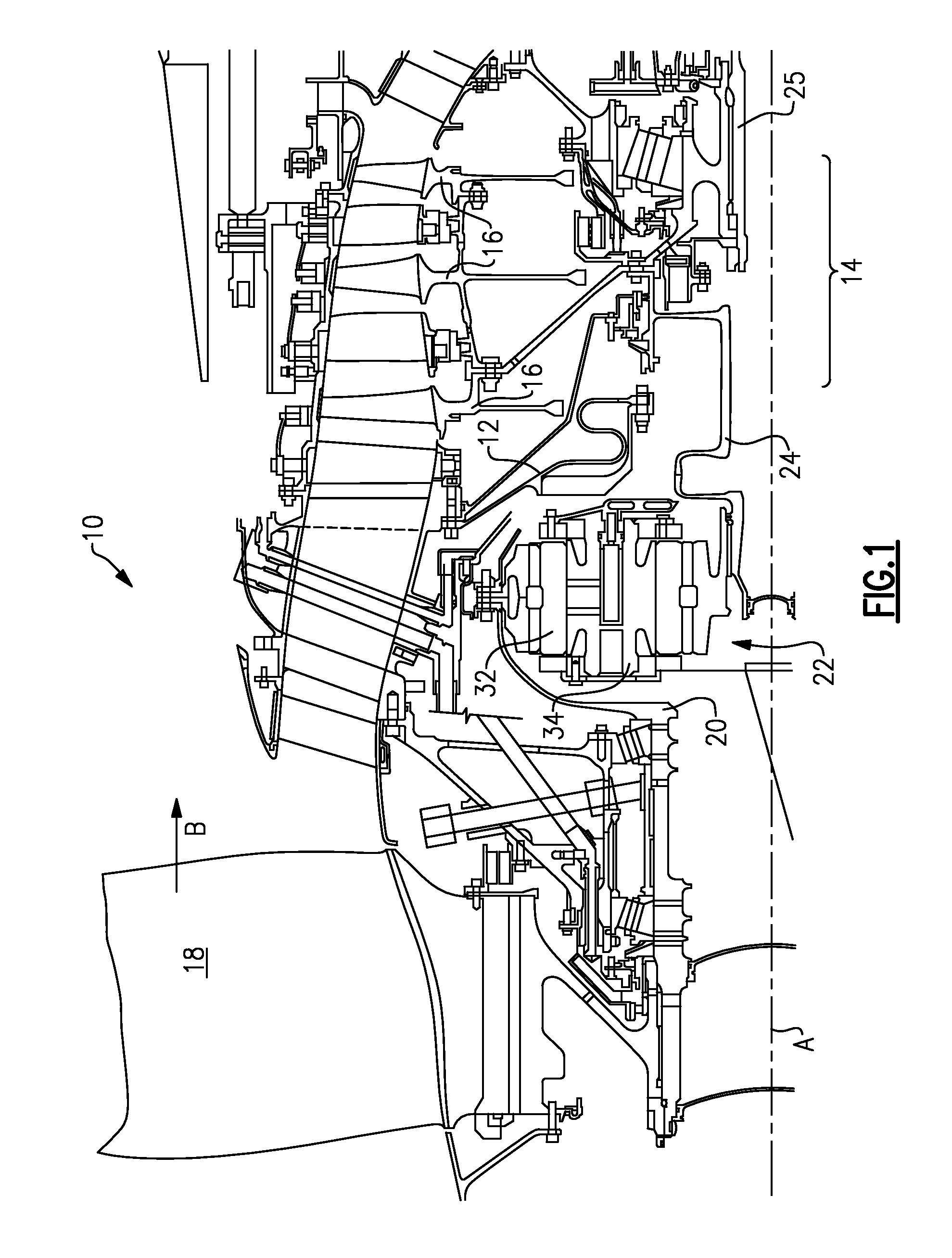
[0031]A portion of a gas turbine engine 10 is shown schematically in FIG. 1. The turbine engine 10 includes a fixed housing 12 that is constructed from numerous pieces secured to one another. A compressor section 14 having compressor hubs 16 with blades are driven by a turbine shaft 25 about an axis A. A turbo fan 18 is supported on a turbo fan shaft 20 that is driven by a compressor shaft 24, which supports the compressor hubs 16, through an epicyclic gear train 22.

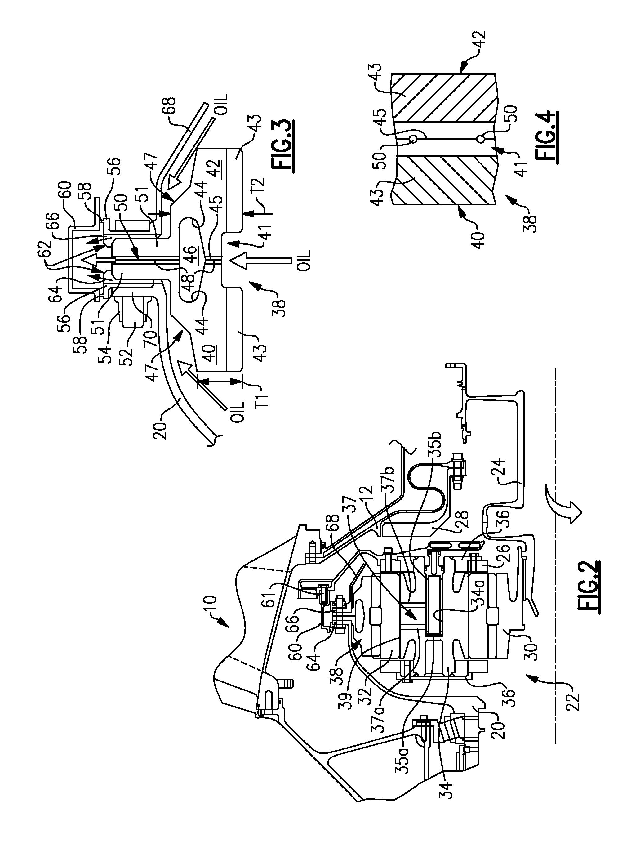
[0032]In the example arrangement shown, the epicyclic gear train 22 is a star gear train. Referring to FIG. 2, the epicyclic gear train 22 includes a sun gear 30 that is connected to the compressor shaft 24, which provides rotational input, by a splined connection. A carrier 26 is fixed to the housing 12 by a torque frame 28 using fingers (not shown) known in the art. The carrier 26 supports star gears 32 using journal bearings 34 that are coupled to the sun gear 30 by meshed interfaces between the teeth of sun and star ...


PUM


Abstract

An epicyclic gear train includes a carrier that supports star gears that mesh with a sun gear. A ring gear surrounds and meshes with the star gears. Each of the star gears is supported on a respective journal bearing. Each journal bearing includes an internal central cavity and at least one passage that extends radially from the internal cavity to a peripheral journal surface of the respective journal bearing. The epicyclic gear train has a gear reduction ratio of greater than or equal to about 2.3.

Description

CROSS REFERENCE TO RELATED APPLICATIONS[0001]The present disclosure is a continuation of U.S. patent application Ser. No. 13 / 340,735, filed Dec. 30, 2011, which is a continuation-in-part of U.S. patent application Ser. No. 11 / 504,220, filed Aug. 15, 2006.BACKGROUND OF THE INVENTION[0002]This invention relates to a ring gear used in an epicyclic gear train of a gas turbine engine.[0003]Gas turbine engines typically employ an epicyclic gear train connected to the turbine section of the engine, which is used to drive the turbo fan. In a typical epicyclic gear train, a sun gear receives rotational input from a turbine shaft through a compressor shaft. A carrier supports intermediate gears that surround and mesh with the sun gear. A ring gear surrounds and meshes with the intermediate gears. In arrangements in which the carrier is fixed against rotation, the intermediate gears are referred to as “star” gears and the ring gear is coupled to an output shaft that supports the turbo fan.[000...

Claims


Application Information

Patent Timeline
Patent Type & Authority Applications(United States)
IPC IPC(8): F01D15/12F16H57/08
CPCF01D5/027F02C7/32F05D2220/36F05D2260/40311F05D2240/70F16H57/0479F16H57/0486F16H2057/085F05D2260/34F16H57/0423
Inventor MCCUNE, MICHAEL E.PORTLOCK, LAWRENCE E.SCHWARZ, FREDERICK M.
Owner MCCUNE MICHAEL E
Why Eureka
Try Eureka