Rich-lean burner

a burner and rich-lean technology, applied in the direction of burners, combustion types, staged combustion, etc., can solve the problems of unsatisfactory noise and vibration

Active Publication Date: 2012-09-27
PALOMA
View PDF1 Cites 26 Cited by
  • Summary
  • Abstract
  • Description
  • Claims
  • Application Information

AI Technical Summary

Benefits of technology

[0010]According to the configuration described above in the first aspect, the partial supply of lean gas into the gap can be ensured without using holes.
[0011]Further, according to the configuration with the additional feature described above in second or third aspect, the recessed portion can be formed at the same time as the at least one of the projections or the other of the first and second partition plates with which the projections are to be in contact are formed. Therefore, the recessed portion can be obtained easily.

Problems solved by technology

With this gap, the basal portions of the pilot flames at its lean-flame port side would likely become unstable, which resultantly causes the pilot flames to flutter, producing undesirable noises and vibrations as the case may be.

Method used


Image

  • Rich-lean burner
  • Rich-lean burner
  • Rich-lean burner

Examples


Embodiment Construction

[0019]Exemplary embodiments of the present invention will be described hereinafter with reference to the accompanying drawings.

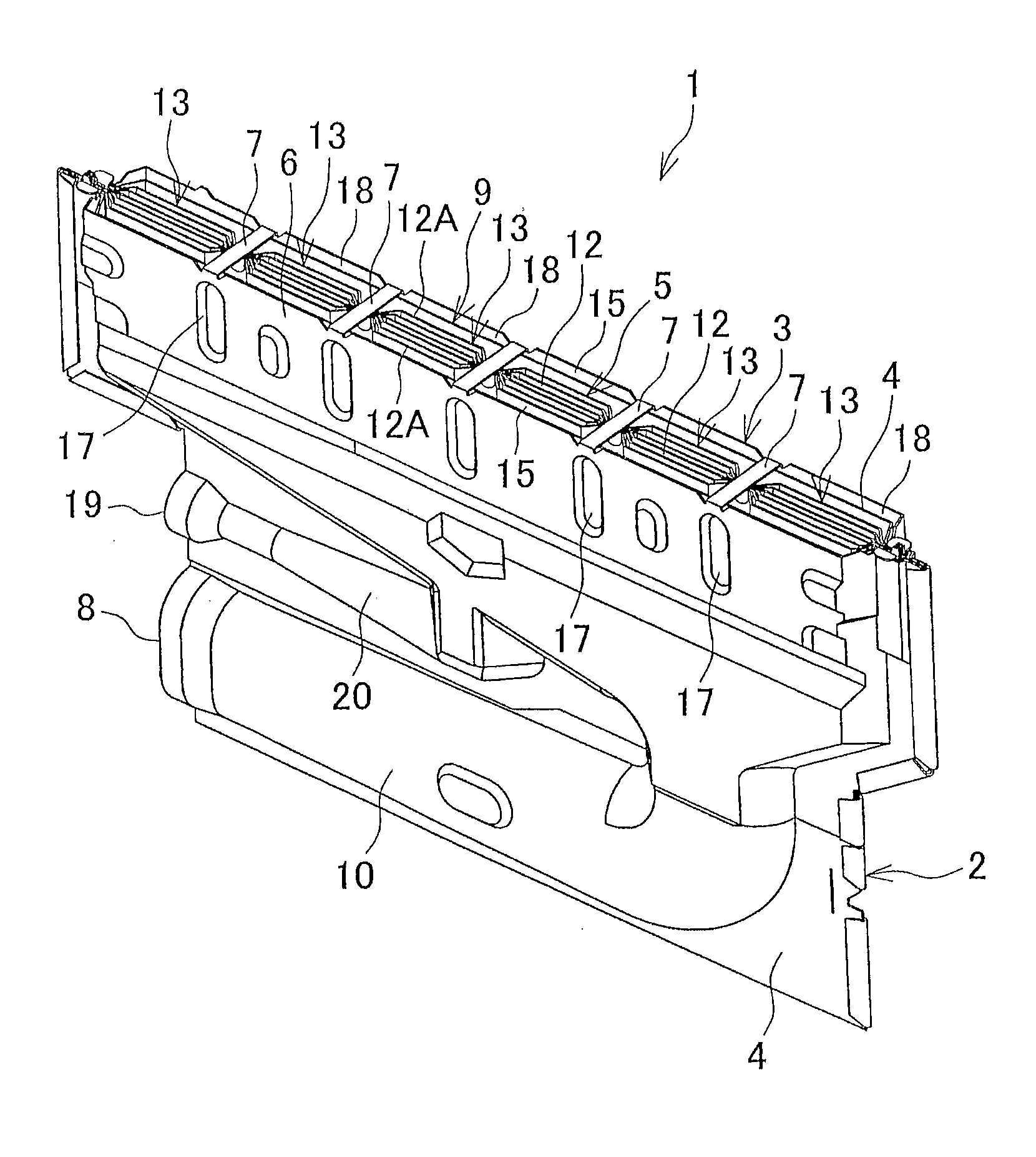
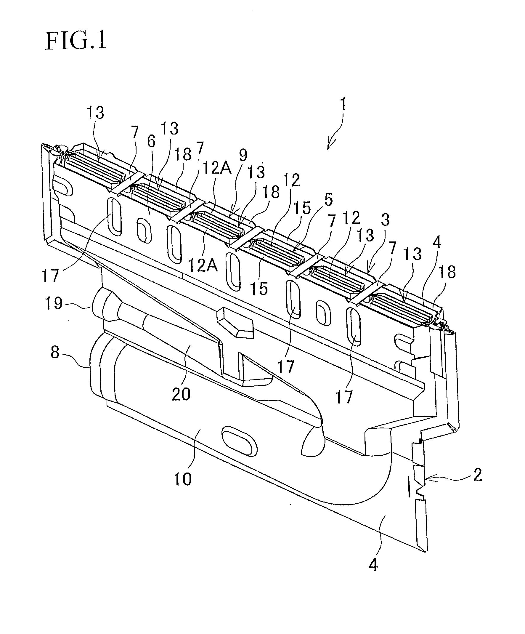
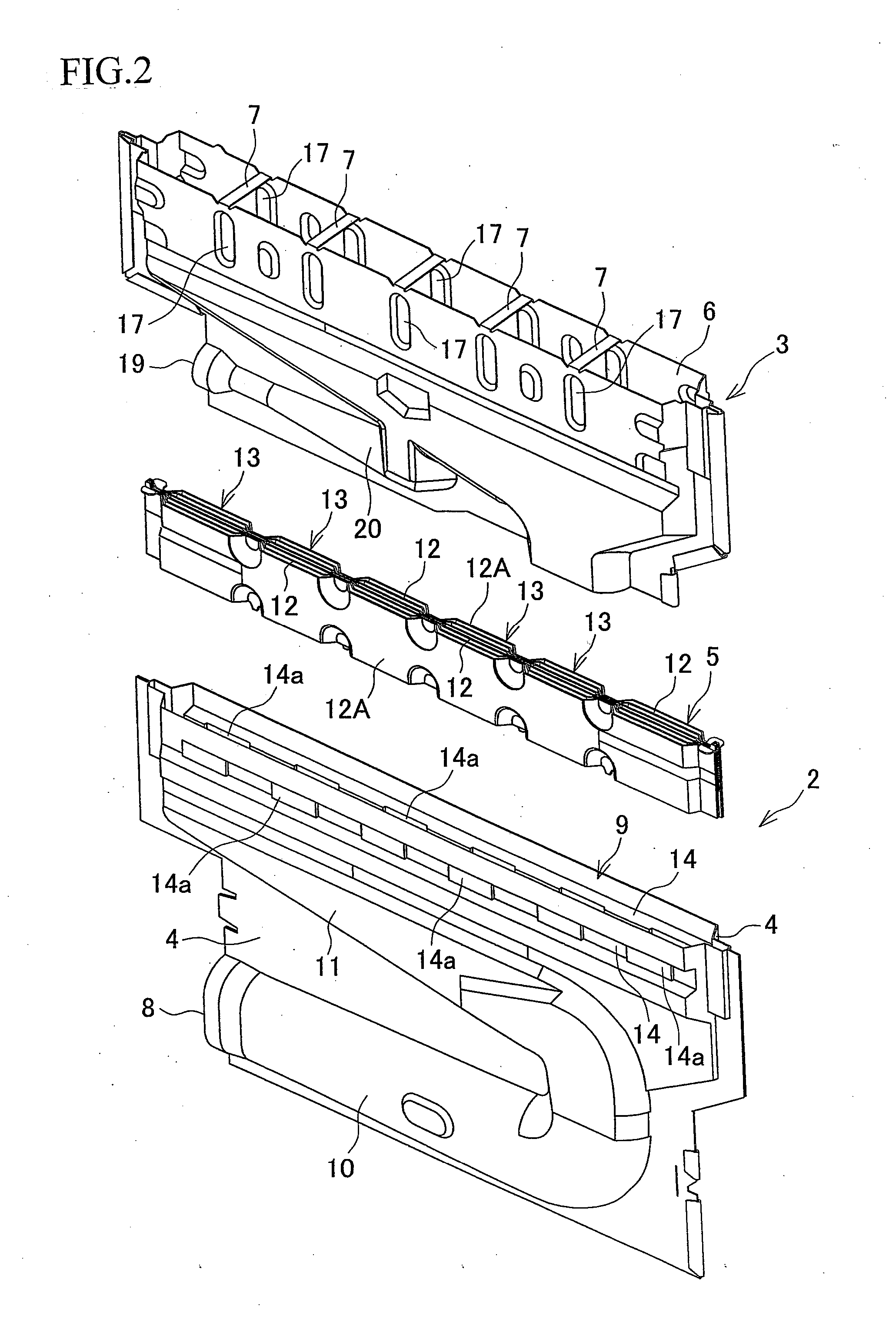
[0020]Referring to FIGS. 1 and 2, a rich-lean burner 1 includes a lean burner unit 2 having lean-flame ports 13 configured to form main flames, and a rich burner unit 3 having rich-flame ports 18 configured to form pilot flames.

[0021]The lean burner unit 2 includes two stamped metal plates 4 which are spot-welded and swaged together to have a generally flat shape. A flame port unit 5 is held between upper portions of the two plates 4. The rich burner unit 3 includes a stamped metal plate 6 which is bent and folded to have a generally flat shape similar to the lean burner unit 2. An upper end of the rich burner unit 3, has openings with connecting pieces 7 left between the openings. The lean burner unit 2 is mounted with its upper portion sandwiched between opposed portions of the plate 6 from their thickness directions, and the rich burner unit 3 is spot-wel...


PUM


Abstract

In a rich-lean burner, a gap formed between a lean-flame port and a rich-flame port is in fluid communication with a supply passage through which a lean gas is to be supplied to the lean-flame port. One or more projections are provided on at least one of partition plates disposed between the gap and the lean-flame port and between the gap and the rich-flame port. A recessed portion is formed at a region adjacent to the lean-flame ports at an interface between the distal end of at least one of the projections protruding from one of the partition plates and the other of the partition plates, the distal end of the at least one of the projections being partially not in contact with the other of the partition plates to provide a clearance through which the lean gas is allowed to be supplied to the gap.

Description

BACKGROUND OF THE INVENTION[0001]This application claims the benefit of Japanese Patent Application Numbers 2011-066421 filed on Mar. 24, 2011, the entirety of which is incorporated by reference.TECHNICAL FIELD[0002]This invention relates to a rich-lean burner (low NOx burner) for use in a gas combustion apparatus such as a water heater, the rich-lean burner including a lean-flame port from which a lean gas is to be supplied, and a rich-flame port which is disposed adjacent to the lean-flame port and from which a rich gas is to be supplied.BACKGROUND ART[0003]In a gas combustion apparatus such as a water heater, a rich-lean burner (low NOx burner) may be used which is configured to form a main flame by burning air-fuel mixture (lean gas) of which the air-fuel ratio is lower than a theoretical air-fuel ratio of the gas at a lean-flame port, and to form a pilot flame by burning air-fuel mixture (rich gas) of which the air-fuel ratio is higher than a theoretical air-fuel ratio of the g...

Claims


Application Information

Patent Timeline
Patent Type & Authority Applications(United States)
IPC IPC(8): F23Q9/00F23D14/46
CPCF23D14/46F23D14/105F23C2201/20F23D14/586F23D14/26
Inventor HOMMA, TSUTOMU
Owner PALOMA
Why Eureka
Try Eureka