Anesthesia Monitoring Device and Method

an anesthesia monitoring and companion lead technology, applied in the field of monitoring and companion lead systems, can solve the problems of not being able to observe and evaluate the response of patients, and the anesthesiologist will not be able to observe and evaluate the patient's response to stimulation, so as to achieve more flexibility in positioning

Inactive Publication Date: 2012-09-27
BOLSER JEFFREY W +1
View PDF22 Cites 22 Cited by
  • Summary
  • Abstract
  • Description
  • Claims
  • Application Information

AI Technical Summary

Benefits of technology

[0005]The present invention includes a monitoring device consol and a companion lead system. The lead system may be applied to the surface of the patient and be under surgical drapes and therefore out of sight of the anesthesiologist. The ability to attach the lead and sensors without regard to visibility allows more flexibility in the positioning of the anesthesiologist in the surgery space and makes it possible to apply an objective standard to identifying problematic muscle movement or activity.

Problems solved by technology

However depending on the procedure these may not be easily observed due to their proximity to the surgical site.
For example, it requires that the anesthesiologist be in a physical position to observe the patient's muscle response; if the anesthesiologist view of the patient's muscle response is blocked due to positioning or sterile draping, the anesthesiologist will not be able to observe and evaluate a patient's response to the stimulation.

Method used


Image

  • Anesthesia Monitoring Device and Method
  • Anesthesia Monitoring Device and Method
  • Anesthesia Monitoring Device and Method

Examples


Embodiment Construction

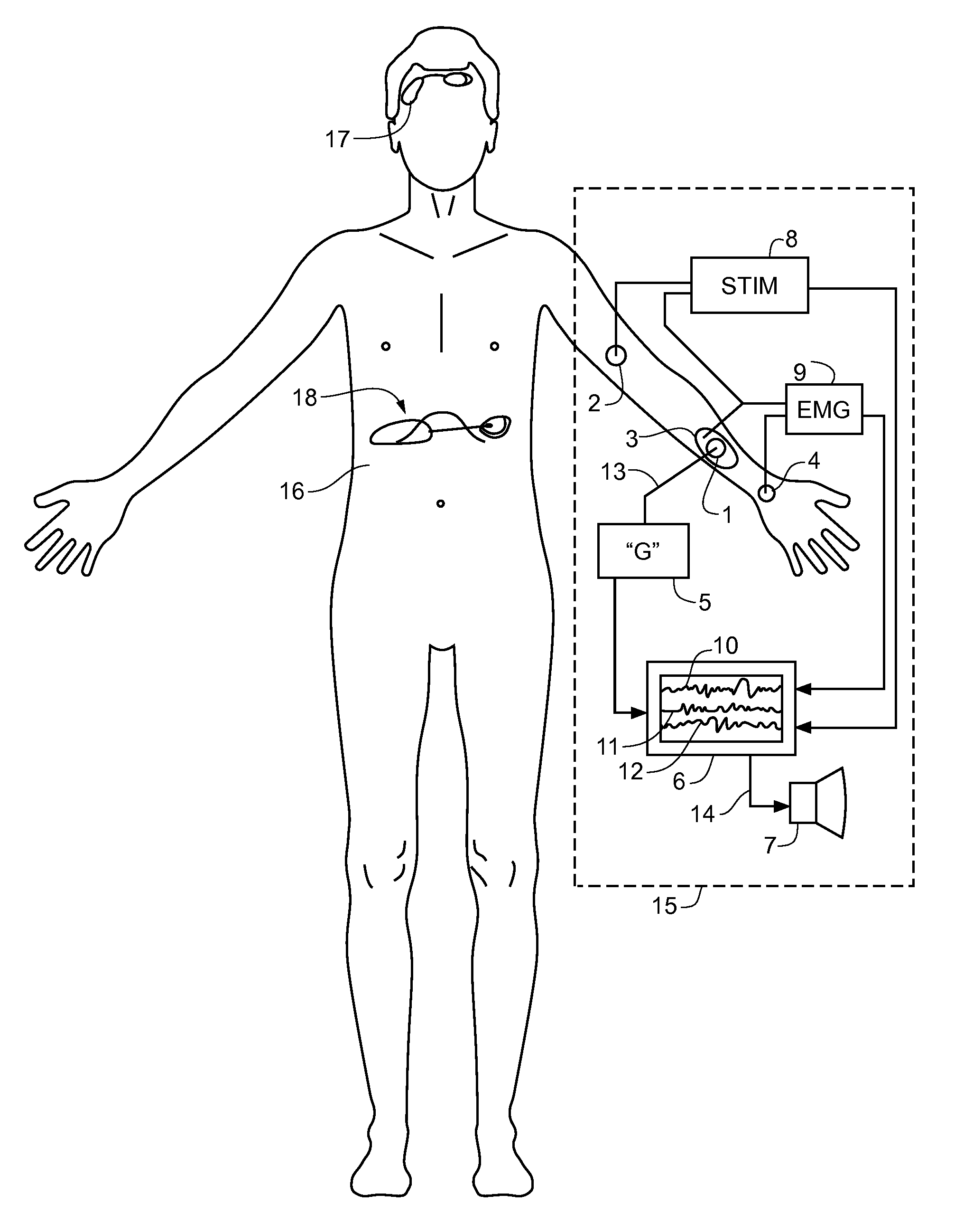
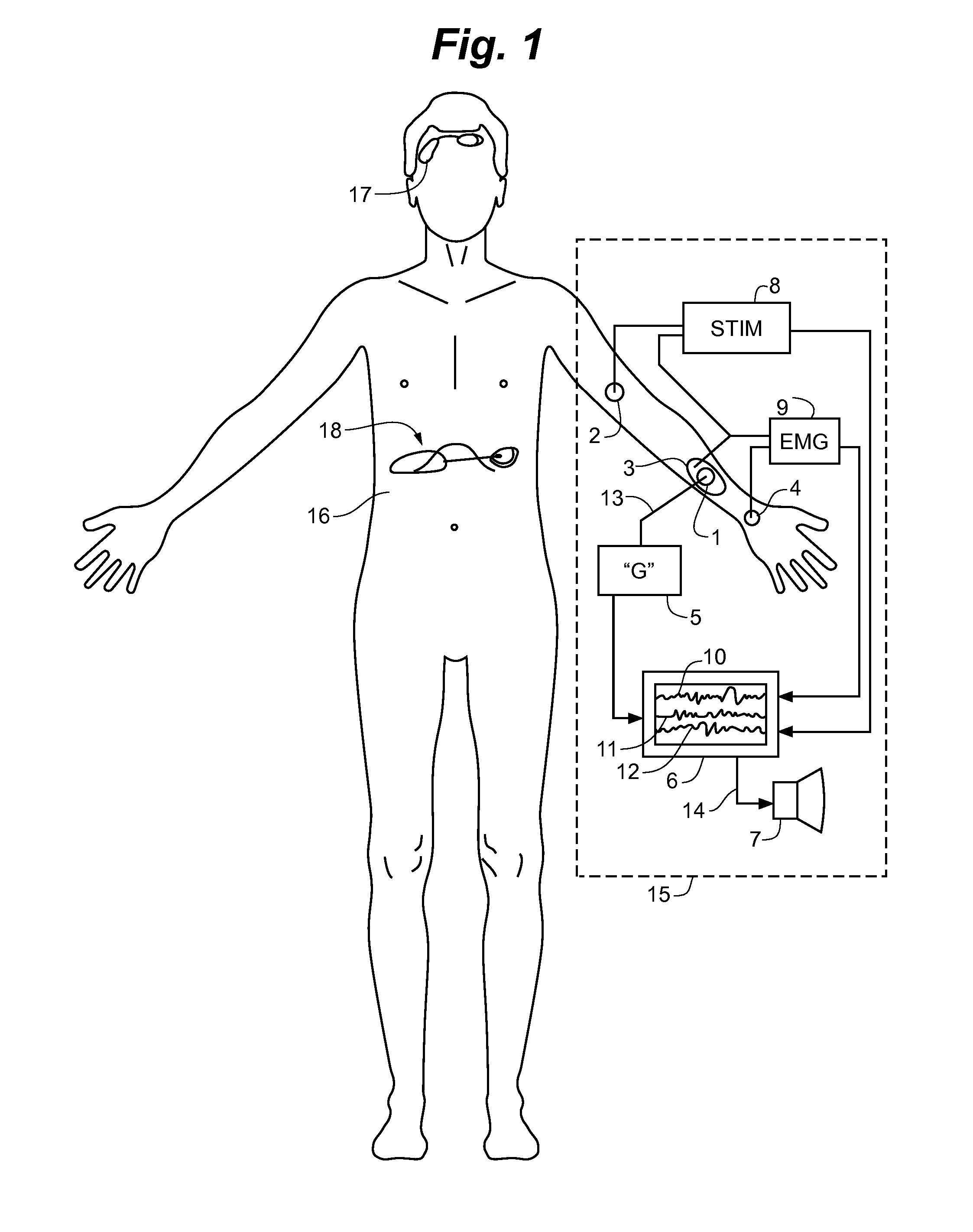
[0017]The invention overall is partitioned into one or more patch electrode systems seen at reference numerals 60, 64 and 62 in FIG. 7. The electrodes systems are connected to a monitoring device 15 that incorporates a visual display 6 that presents a tracing 11 reflecting acceleration or motion data taken from a skin mounted accelerometer along with a tracing 10 presenting the real time electromyography sensor data. A further tracing 12 may display the stimulator output. This overall partitioning is seen in FIG. 7 where a user switch 66 may select between patch / sensor systems typified by patch / sensor 60 or 64 or 62. Although multiple patch systems are contemplated the disclosure is clarified by referring to a single patch system embodiment.

[0018]In one embodiment, as depicted in FIG. 1, the anesthesia monitor device of the invention 15 includes one or more electrode patches at reference numeral 2 and reference numeral 3. In this embodiment an accelerometer 1 is incorporated in patc...


PUM


Abstract

A patient monitoring system to measure the depth of anesthesia, and to provide a physician warning during a surgical procedure.

Description

CROSS REFERENCE TO RELATED CASES[0001]The present application is the utility conversion of U.S. Provisional Patent Application Ser. No. 61 / 383,461, filed Sep. 16, 2010 entitled Anesthesia Monitoring Device and Method. The provisional application is incorporated by reference in its entirety.FIELD OF THE INVENTION[0002]The present invention relates generally to a monitor and companion lead system used in a surgical suite to monitor a patient undergoing a surgical procedure under anesthesia.BACKGROUND OF THE INVENTION[0003]In some instances, modern anesthesia employs paralytic agents to prevent tense musculature from interfering with surgical interventions. One method that has been employed to test for muscle paralysis uses a conventional nerve stimulator that applies an electrical signal to skin electrodes and evokes a muscle twitch that is observed by the anesthesiologist. Depending on the location for the surgery, the application of the stimulation may be applied to the radial nerve...

Claims


Application Information

Patent Timeline
Patent Type & Authority Applications(United States)
IPC IPC(8): A61B5/0488A61B5/11
CPCA61B5/0492A61B5/1107A61B5/6833A61B2562/0219A61B2560/0412A61N1/0492A61N1/36003A61N1/36014A61B2505/05A61N1/0452A61B5/296
Inventor BOLSER, JEFFREY W.BOLSER, CORINNE ELIZABETH
Owner BOLSER JEFFREY W
Why Eureka
Try Eureka