Method and system to compensate for temperature and pressure in piezo resistive devices

Active Publication Date: 2012-10-04
NXP USA INC
View PDF9 Cites 4 Cited by
  • Summary
  • Abstract
  • Description
  • Claims
  • Application Information

AI Technical Summary

Problems solved by technology

If the PRT is not balanced with respect to pressure, large errors result in the computation of temperature.
However, attempting to balance a PRT with respect to pressure is difficult to achieve and places a heavy constraint on the design and manufacture of PRTs.

Method used


Image

  • Method and system to compensate for temperature and pressure in piezo resistive devices
  • Method and system to compensate for temperature and pressure in piezo resistive devices
  • Method and system to compensate for temperature and pressure in piezo resistive devices

Examples


Embodiment Construction

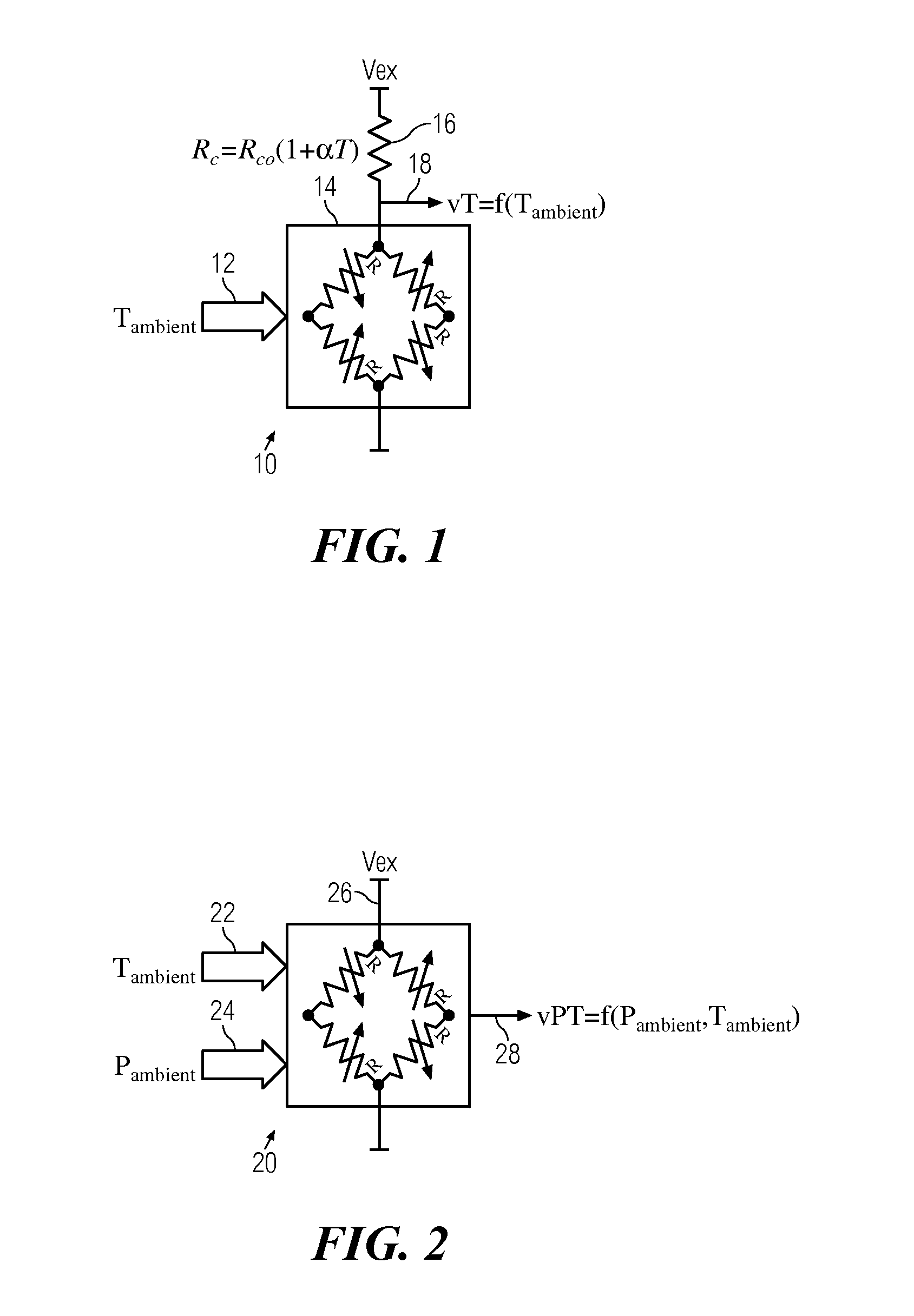
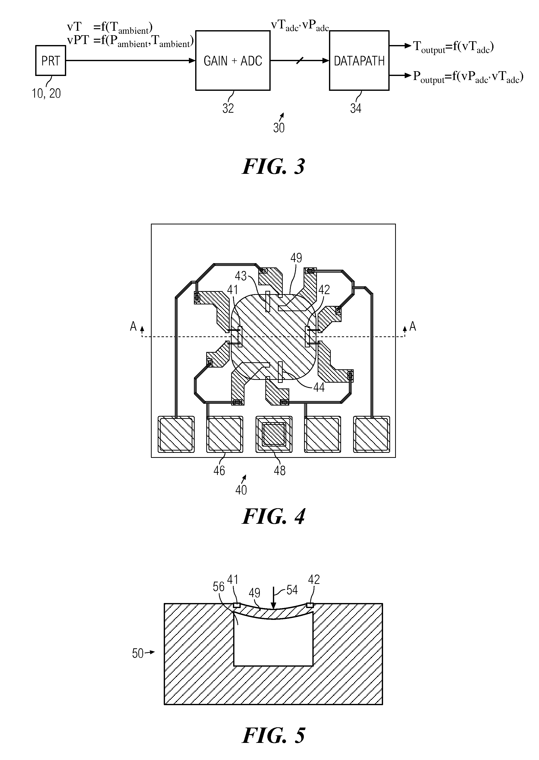
[0019]In one embodiment of the present invention, a method of calibrating a piezo resistive device having a piezo resistive element with a fluctuating resistivity in the piezo resistive device and signals representative of the temperature and pressure readings of the piezo resistive device includes calculating a first temperature as a function of the signal representative of temperature reading of the piezo resistive device, and calculating an actual pressure as a function of the first temperature and the signal representative of pressure reading of the piezo resistive device.

[0020]Another embodiment of the invention comprises calculating an actual temperature as a function of the first temperature and the actual pressure. The calculating of the actual temperature may be performed with a constant of the actual pressure calculated for calibrating the piezo resistive device. The constant may be determined empirically by determining a value of the constant of the actual pressure. The c...


PUM


Abstract

A method and system to calibrate temperature and pressure in piezo resistive devices for non-linear sensors having two variables, where a piezo resistive device such as a piezo resistive transducer (PRT) used for example in a pressure sensor system is calibrated to calculate actual / ambient temperature and pressure even though the PRT impedance is unbalanced relative to pressure.

Description

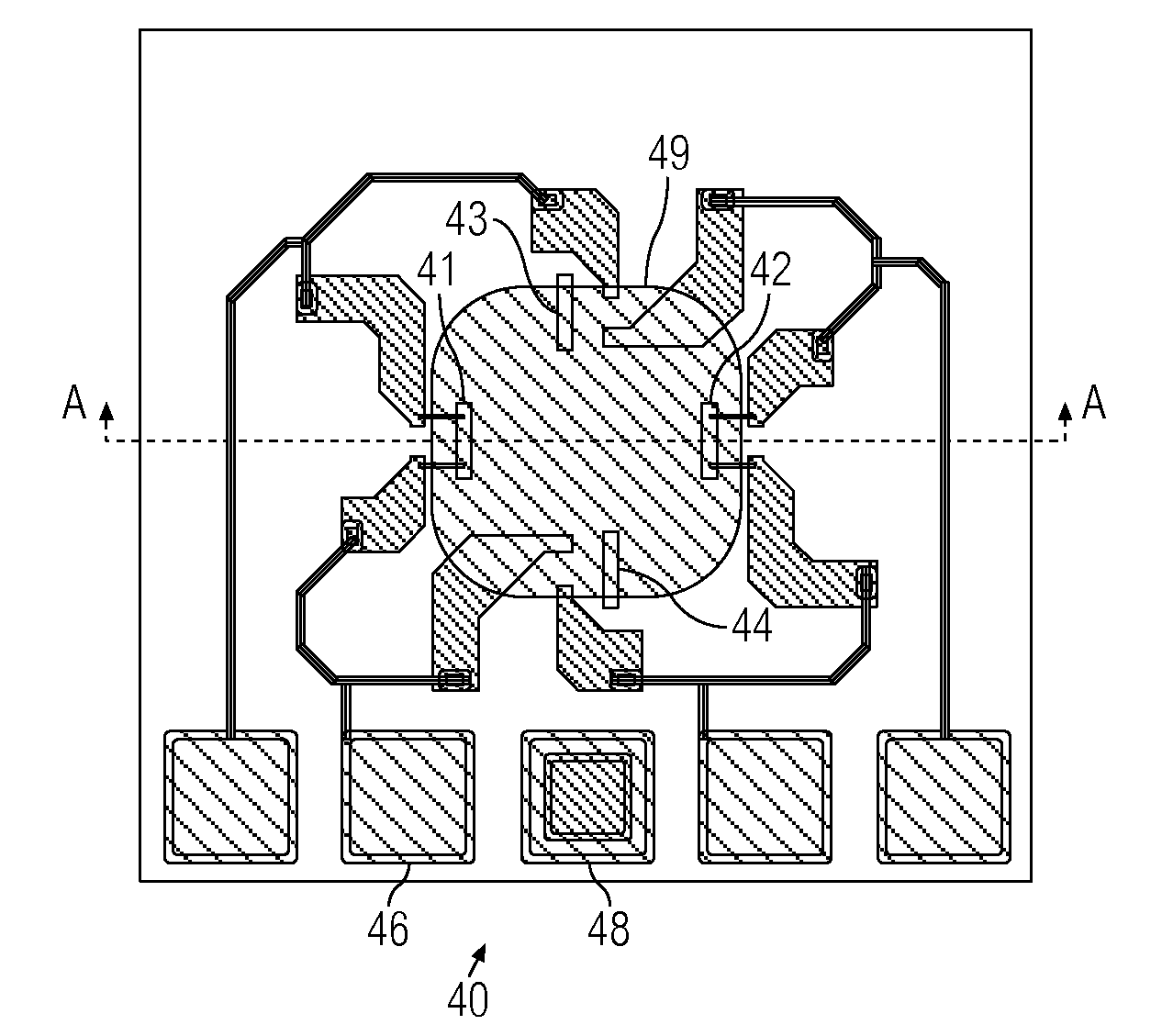
BACKGROUND OF THE INVENTION[0001]The present invention relates generally to pressure sensors and, more particularly, to non-linear sensors having two variables with cross-dependency.[0002]Piezo resistive devices, such as piezo resistive transducers (PRT), are commonly used in commercial systems such as stress or pressure sensor systems. Such PRTs are typically implemented in integrated circuits and semiconductor devices. In accordance with the piezo resistive effect, the resistivity of piezo resistive elements changes in response to strain from the applied mechanical or physical stress to the piezo resistive element. In integrated circuits and semiconductor devices, the piezo resistive elements of the PRT are arranged to be in contact with a diaphragm such that a force or pressure applied to the diaphragm and the PRT converts the mechanical stress on the piezo resistive elements into differential electrical outputs. This property is used to measure ambient pressure.[0003]The resisti...

Claims


Application Information

Patent Timeline
IPC IPC(8): G01L27/00
CPCG01L27/002G01L9/065G01L27/005
Inventor KRISHNA, SIDDHARTHA GOPALDAWSON, CHAD S.VARMA, VIKRAM
Owner NXP USA INC
Why Eureka
Try Eureka