Switchgear assembly

Active Publication Date: 2012-10-04
SCHNEIDER ELECTRIC INFRASTRUCTURE
View PDF7 Cites 5 Cited by
  • Summary
  • Abstract
  • Description
  • Claims
  • Application Information

AI Technical Summary

Benefits of technology

[0014]It is yet another object of the invention to provide a switchgear assembly which mitigates the need for changing the viewing angle to view polyphase contacts.
[0015]It is yet another object of the invention to provide a switchgear assembly having a simplified operation.
[0016]It is yet another object of the invention to provide a switchgear assembly with additional safety measures.
[0017]It is yet another object of the invention to provide a switchgear assembly which is economic in construction and operation.
[0018]It is yet another object of the invention to provide a switchgear assembly which is compact in design.
[0019]According to an aspec

Problems solved by technology

However, increasing power levels and voltages have made open manually-operated switches very dangerous to use for anything other than isolation of a de-energized circuit.
Since it is tedious to view the contacts in an enclosed housing, and the result yielded by the sensors is not 100 percent guaranteed, there is a need for a manual mechanism to view the internal parts in the enclosed electrical equipment.
In case of gas insulated switchgears, the position of the switch and contacts cannot be viewed from the front side even if a front inspection window is provided due to its

Method used


Image

  • Switchgear assembly
  • Switchgear assembly
  • Switchgear assembly

Examples


Example

[0024]The invention may be better understood and further advantages and uses thereof more readily apparent when considered in view of the following detailed description of exemplary embodiments taken with the accompanying drawings. These embodiments describe only a few of the various ways in which the principles of various other embodiments may be realized and the described embodiments are intended to include all such embodiments and their equivalents and the reference numerals used in the accompanying drawings correspond to the like elements throughout the description.

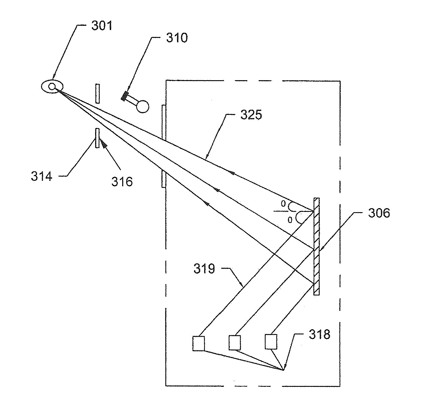
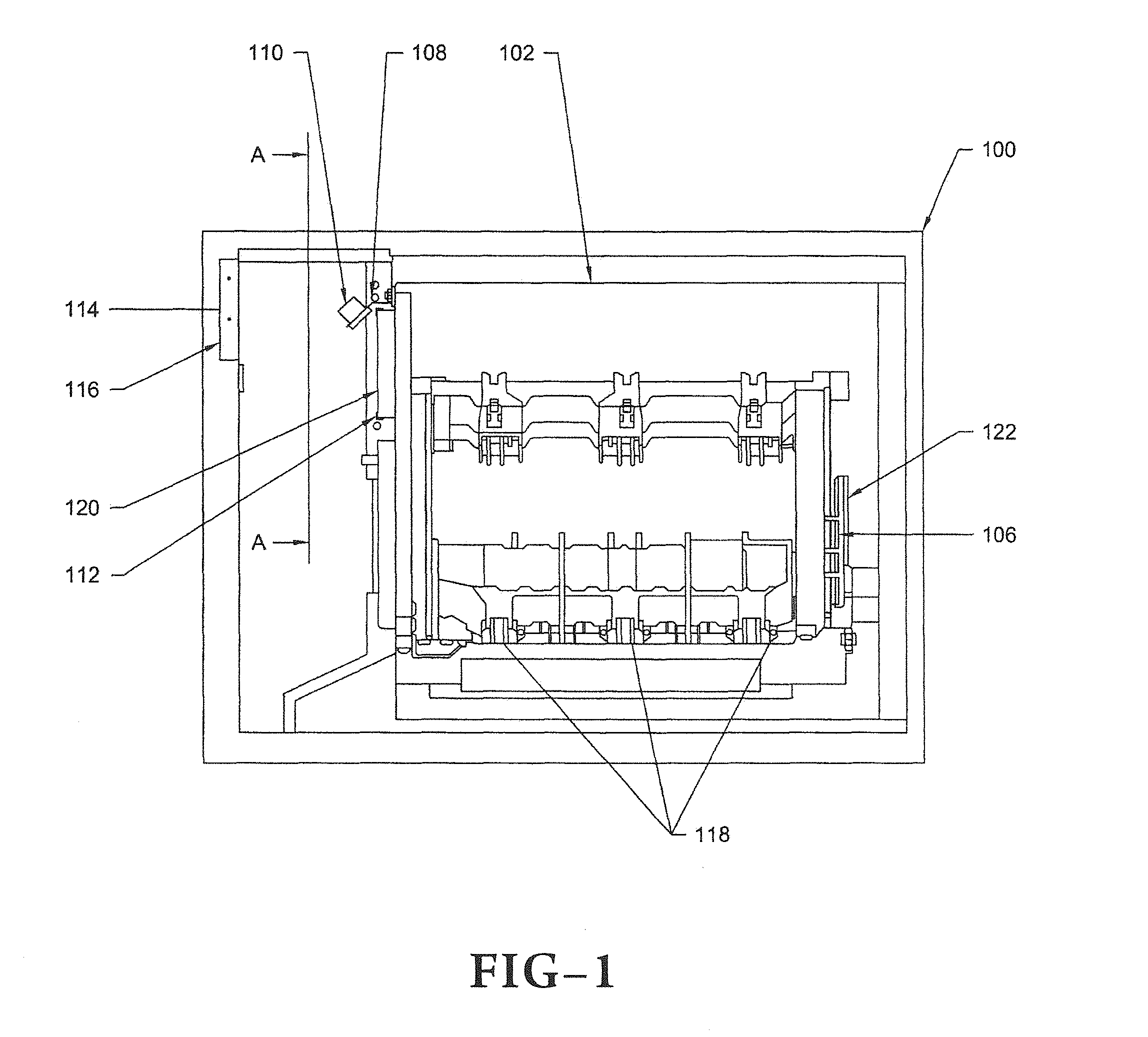
[0025]FIG. 1 illustrates a switchgear assembly (100) having a tank housing (102) which encapsulates a rotary knife blade contact earthing or grounding system (110), a reflecting surface (106) and high voltage equipment which needs to be secured from the operator for safety of the operator. Tank housing (102) has a bracket (108) welded on to it for mounting at least one external light source or illuminating device (110...


PUM


Abstract

A switchgear assembly includes a tank housing encapsulating switching contacts which are viewable through a transparent viewing port after illumination of the contacts. A reflective optical device for observing the position of the switching contacts is used to view the contacts at a safe distance outside of the tank housing through the transparent viewing port. An illuminating device is used to illuminate the switching contacts by directing the light from the illuminating device on the switch contacts.

Description

[0001]This application claims priority of Indian Application Serial No. 848 / DEL / 2001 filed on Mar. 28, 2011.BACKGROUND OF THE INVENTION[0002]1. Field of the Invention[0003]The present invention relates to electrical equipment. In particular, this invention relates to systems for detecting the state of electrical contacts in enclosed electrical equipment such as switchgears. More particularly, this invention relates to viewing the rotary knife blade contact earthing or grounding system in electrical equipment such as switchgears.[0004]2. Description of the Prior Art[0005]Switchgears are used in the electric power systems or grids and basically refer to the combination of disconnectors, fuses and / or circuit breakers used to isolate electrical equipment from the mains or alternating current (AC) electrical power supply. Switchgears are used to de-energize equipment to allow work to be done and to clear faults in the electrical equipment. This type of equipment is important because it i...

Claims


Application Information

Patent Timeline
IPC IPC(8): H01H9/16
CPCH01H1/0015H02B1/306H02B13/045H01H2009/0292
Inventor RAORANE, DEEPAKAGRAWAL, ASHISH
Owner SCHNEIDER ELECTRIC INFRASTRUCTURE
Why Eureka
Try Eureka