Image forming apparatus to detect density unevenness and density unevenness detection device

a technology of density unevenness and detection device, which is applied in the field of image forming apparatus, can solve problems such as image quality declin

Inactive Publication Date: 2012-10-04
KONICA MINOLTA INC
View PDF12 Cites 2 Cited by
  • Summary
  • Abstract
  • Description
  • Claims
  • Application Information

AI Technical Summary

Benefits of technology

[0008][1] To achieve at least one of the above mentioned objects, an image forming apparatus reflecting one aspect of the present invention comprises: an image forming section to subject image formation of a linear test pattern; a measurement section to measure a line width of one line of the linear test pattern at a plurality of measurement points; and a detection section to detect density unevenness, wherein the detection section converts the measured line width into density and, eliminates a measurement point where the measured line width thereof is less than a predetermined value to detect density unevenness in an extending direction of the linear test pattern.
[0022][6] To achieve at least one of the above mentioned objects, a density unevenness detection device reflecting one aspect of the present invention comprises; an output section to output data of a linear test pattern: an acquisition section acquires image data which is obtained and read the linear test pattern with a predetermined reading device in which the linear test pattern is subjected to image formation by a predetermined image forming apparatus based on the data to be output by the output section: a detection section to measure a line width of one line of the linear test pattern at a plurality of measurement points by which image formation is carried out with the image forming apparatus based on the image data acquired by the acquisition section, to convert the measured line width into density, and to eliminate a measurement point where the measured line width thereof is at most a predetermined value to detect density unevenness in an extending direction of the linear test pattern on the image forming apparatus.

Problems solved by technology

Conventionally, in image forming apparatuses such as printers, copiers, and multifunction peripherals, due to the change of characteristics caused by product deterioration and parts replacement, density unevenness has occasionally caused a decrease in image quality.

Method used


Image

  • Image forming apparatus to detect density unevenness and density unevenness detection device
  • Image forming apparatus to detect density unevenness and density unevenness detection device
  • Image forming apparatus to detect density unevenness and density unevenness detection device

Examples


Embodiment Construction

[0043]An embodiment of the present invention will now be described with reference to the drawings.

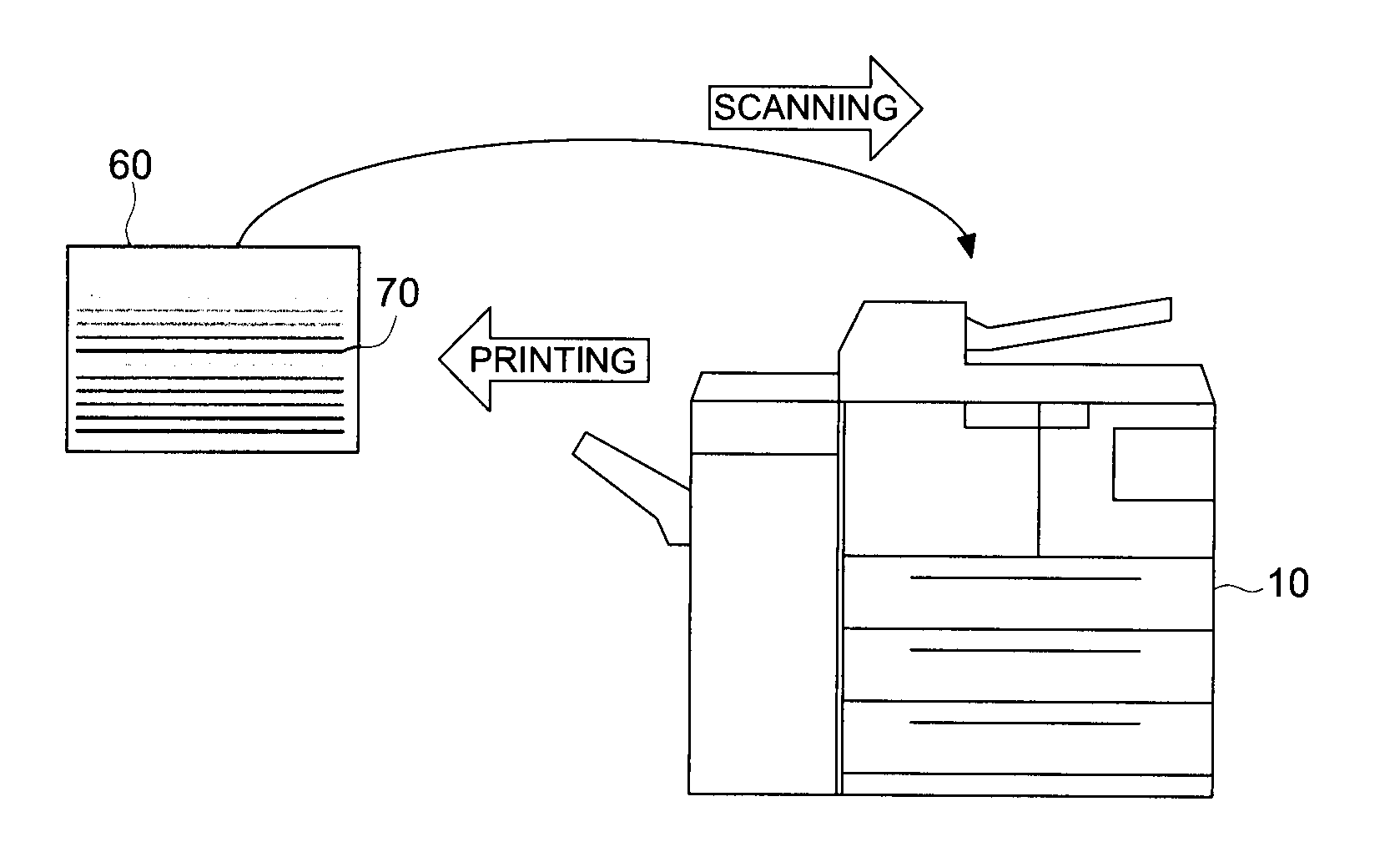
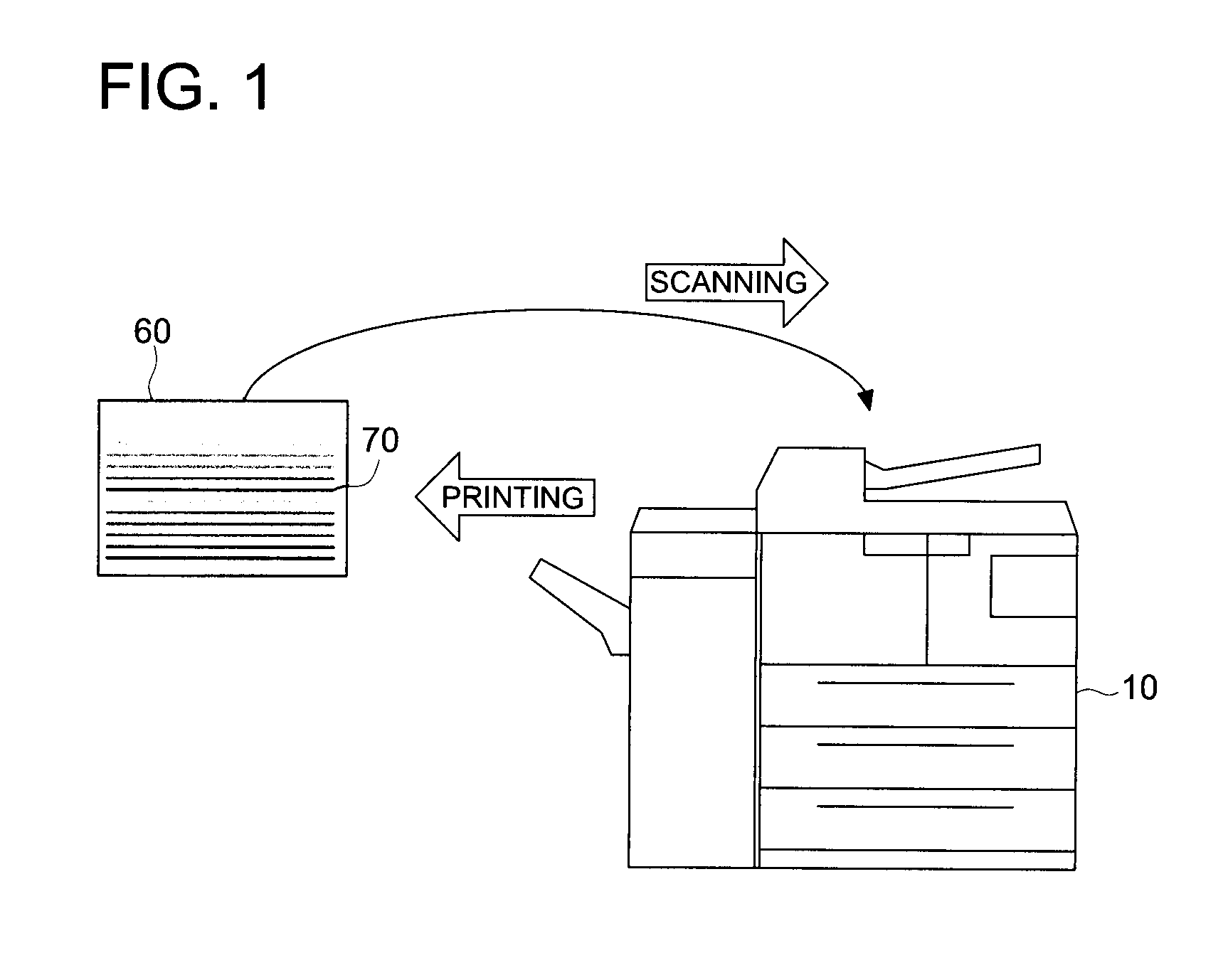
[0044]FIG. 1 shows a workflow during detection of density unevenness using an image forming apparatus 10 according to the embodiment of the present invention. The image forming apparatus 10 is a so-called multifunction peripheral provided with functions to execute jobs such as a copying job in which an original document is optically read and a reproduced image is formed on a recording sheet, a scanning job in which image data of the read original document is stored in a file and transmitted to an external device, and a PC printing job in which an image relevant to print data having been received from a terminal device such as a personal computer is formed on a recording sheet. The image forming apparatus 10 repeatedly forms an image per line in the main scanning direction as the position is shifted in the vertical scanning direction at right angles to the main scanning direction to form...


PUM


Abstract

An image forming apparatus comprising: an image forming section to carry out image formation of a linear test pattern; a measurement section to measure a line width of one line of the linear test pattern at a plurality of measurement points; and a detection section to detect density unevenness, wherein the detection section converts the measured line width into density and, eliminates a measurement point where the measured line width thereof is at most a predetermined value to detect density unevenness in an extending direction of the linear test pattern.

Description

RELATED APPLICATION[0001]The present application is based on Patent Application No. 2011-69208 filed at the Japan Patent Office on Mar. 28, 2011 and which is hereby incorporated herein in its entirety.TECHNICAL FIELD[0002]The present invention relates to an image forming apparatus to detect density unevenness resulting from the image forming apparatus.[0003]Conventionally, in image forming apparatuses such as printers, copiers, and multifunction peripherals, due to the change of characteristics caused by product deterioration and parts replacement, density unevenness has occasionally caused a decrease in image quality. To inhibit the decrease of image quality, as a measurement chart, a patch pattern 80 having a plurality of gradations for each color as sown in FIG. 10 is formed and then its image quality is measured and corrected.[0004]Further, a technique is known in which when a line having a given width is subjected to image formation, by use of the fact that there is a correlati...

Claims


Application Information

Patent Timeline
Patent Type & Authority Applications(United States)
IPC IPC(8): H04N1/00
CPCH04N1/00015H04N1/00034H04N1/00045H04N1/407H04N1/00087H04N1/4078H04N1/00053
Inventor IKEDA, MAKOTO
Owner KONICA MINOLTA INC
Why Eureka
Try Eureka