Exercise device

Active Publication Date: 2012-10-04
AGOSTINI SCOTT C
View PDF24 Cites 37 Cited by
  • Summary
  • Abstract
  • Description
  • Claims
  • Application Information

AI Technical Summary

Benefits of technology

[0012]According to one implementation, the exercise device includes a planar support surface including a first face, an opposing second face, and a sidewall extending between the first face and the second face. The support surface may include one or more handles to allow a user to easily grab onto the device. A rolling joint is coupled to the second face and is configured to allow the exercise device to move about a planar surface, such as a floor or wall. The rolling joint includes a joint wall extending from the second face of the support surface to define a cavity configured to receive a rolling ball which facilitates such motion of the exerc

Problems solved by technology

Although such gyms and fitness centers may facilitate routine exercise for certain individuals, there are various drawbacks associated with gyms and fitness centers.
One drawback is that the gyms/fitness centers generally require membership for access into their facilities.
The membership agreements may require a long-term commitment from the individual, which may add up to a significant expense for the individual.
Another drawback is that it may be difficult for some individuals to make time in their day-to-day schedules to go to the gyms/fitness c

Method used


Image

  • Exercise device
  • Exercise device
  • Exercise device

Examples


first embodiment

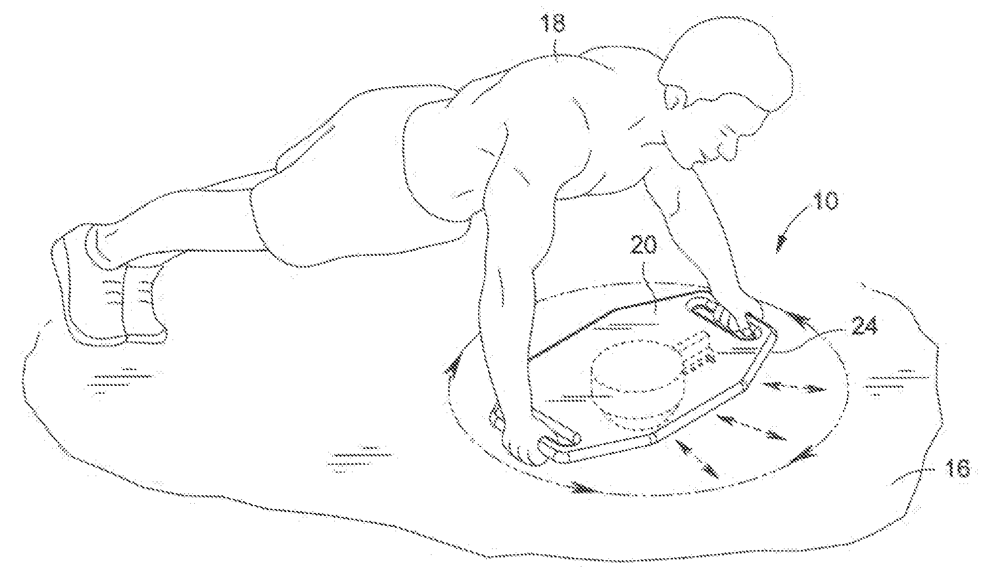
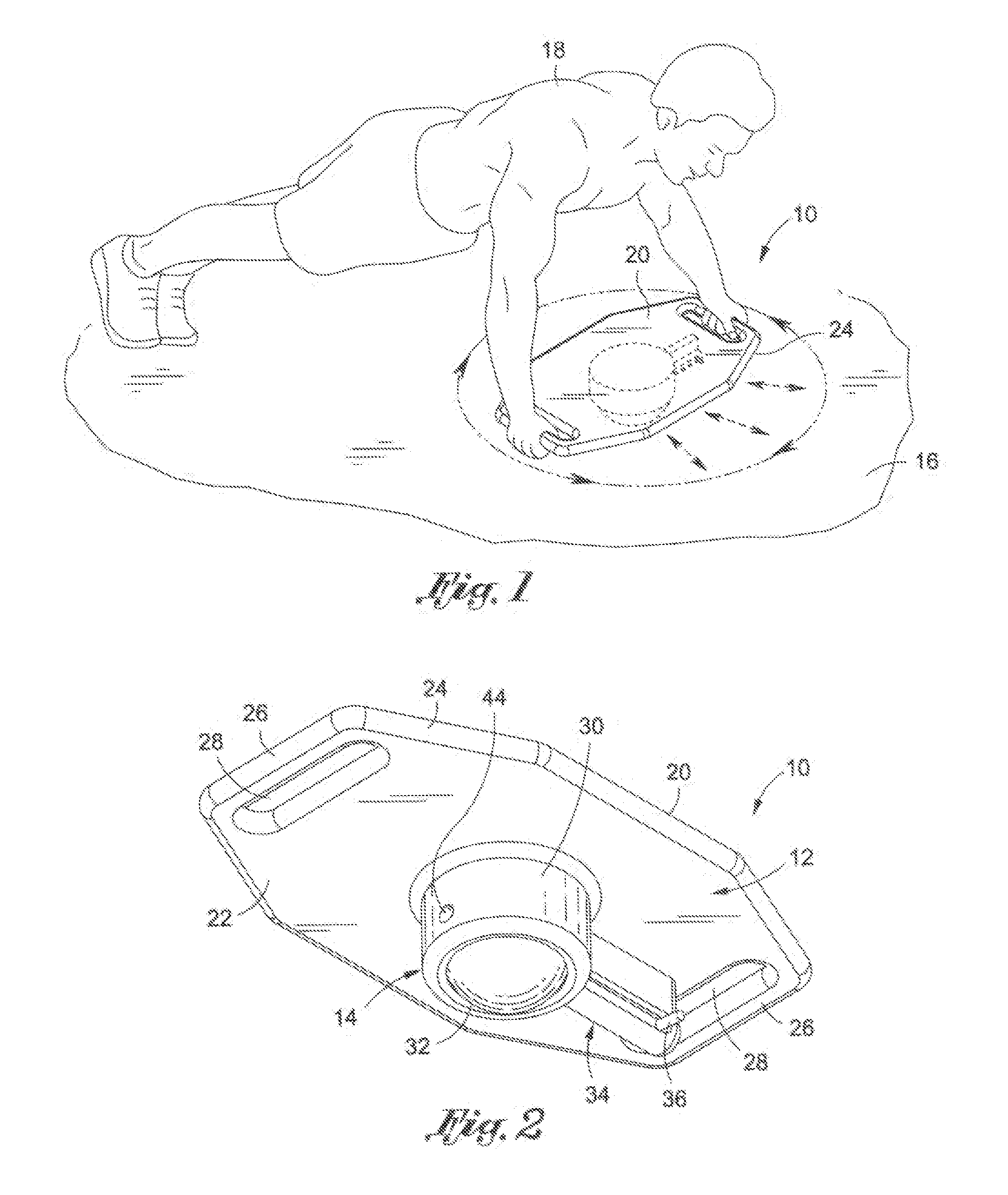
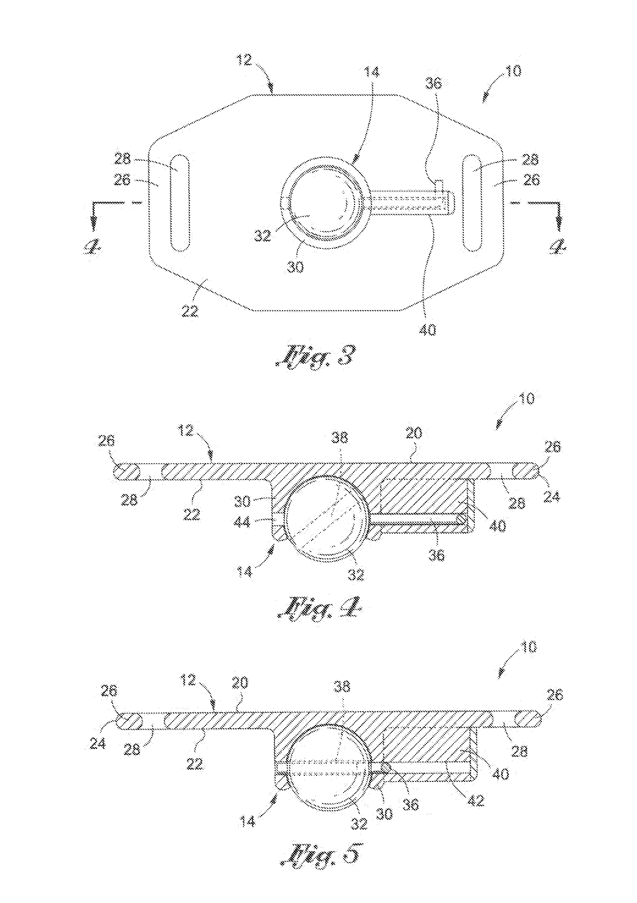
[0045]Referring now to FIGS. 1-5, there is shown an exercise device 10 comprised of a support plate 12 and a rolling joint 14 attached to the support plate 12. When the exercise device 10 is placed against a planer surface 16, such as the floor or a wall, the exercise device 10 may be moved about the surface 16 in a circular manner or an axial manner. A user 18 may grip the support plate 12 at opposed locations thereof and selectively roll the device 10 outward, backward, and sideward to workout various muscle groups, including the abs and back. The rolling joint 14 advantageously allows the device 10 to achieve a 360° freedom of movement to broaden the range of exercise motion achievable by the device 10. In this regard, the device 10 is not merely limited to movement along a single axis, rather, the device 10 may be selectively moved by the user 18 along several different axes, as well as in a curved motion.

[0046]The support plate 12 defines a first face 20, an opposing second fac...

second embodiment

[0053]Referring now to FIG. 6, there is shown a bottom view of the exercise device 60. As described in more detail below, the primary distinction between the exercise device 60 shown in FIG. 6, and the exercise device 10 shown in FIGS. 1-5 lays in the particular configuration of the support surface 62 and a locking mechanism 64.

[0054]The support surface 62 includes a first face and an opposing second face 66. The periphery of the support surface 62 is defined by eight substantially equal edges to define an octagonal shape. The support surface 62 additionally includes four handles 68, arranged in two opposed pairs. Each handle 68 is defined by an opening 70 extending through the support surface 62 from the first face to the second face 66. The additional handles 68 (relative to the device 10 depicted in FIGS. 1-5, and discussed above) allows the user to grip the device 60 at several locations thereof. Although the embodiment in FIG. 6 shows four handles 68, it is understood that fewe...


PUM


Abstract

Provided is an exercise device including a planar support surface and a rolling joint which is configured to enable a 360° range of motion for the exercise device. In this regard, the user may roll the exercise device along a planar surface in a forward-and-backward motion, a side-to-side motion, or in an arcuate or circular motion.

Description

CROSS-REFERENCE TO RELATED APPLICATIONS[0001]This application claims the benefit of U.S. Provisional Application No. 61 / 469,989, filed Mar. 31, 2011 and U.S. Provisional Application No. 61 / 478,358, filed Apr. 22, 2011.STATEMENT RE: FEDERALLY SPONSORED RESEARCH / DEVELOPMENT[0002]Not ApplicableBACKGROUND OF THE INVENTION[0003]1. Technical Field[0004]The present invention relates generally to exercise devices, and more specifically, to an exercise device including a ball and socket arrangement mounted to a support surface to achieve 360° freedom of movement.[0005]2. Description of the Related Art[0006]It is well-known that routine exercise is good for both the body and mind. Along these lines, each community typically includes a gym or fitness center where individuals can access a wide variety of exercise equipment. Although such gyms and fitness centers may facilitate routine exercise for certain individuals, there are various drawbacks associated with gyms and fitness centers. One dra...

Claims


Application Information

Patent Timeline
IPC IPC(8): A63B21/00
CPCA63B22/18A63B23/1236A63B22/203A63B21/0004A63B26/003A63B21/4035A63B21/4043
Inventor AGOSTINI, SCOTT C.
Owner AGOSTINI SCOTT C
Why Eureka
Try Eureka