Electronic endoscope

a technology of endoscope and elongation, which is applied in the field of elongation endoscope, can solve the problems of difficult to change the direction and the difficulty of the capturing optical system to so as to facilitate the focus on the surface of the target and reduce the diameter of the distal portion

Inactive Publication Date: 2012-10-04
FUJIFILM CORP
View PDF12 Cites 131 Cited by
  • Summary
  • Abstract
  • Description
  • Claims
  • Application Information

AI Technical Summary

Benefits of technology

The present invention relates to a method for focusing on a target using a side-viewing capturing optical system. The invention states that the best focus position is located on the outer surface of the distal portion, which makes it easier to focus on the target and reduces the size of the distal portion.

Problems solved by technology

The technical problem addressed in this patent is the difficulty of focusing on a target's surface during magnifying observation using an electronic endoscope, especially when the distal end portion gets too close to the target's surface. The patent proposes a solution by adding a hood to the distal portion of the insert section to ensure a predetermined distance between the capturing optical system and the target's surface, but this increases the size of the distal portion and makes it difficult to change the direction of observation.

Method used


Image

  • Electronic endoscope
  • Electronic endoscope
  • Electronic endoscope

Examples


first embodiment

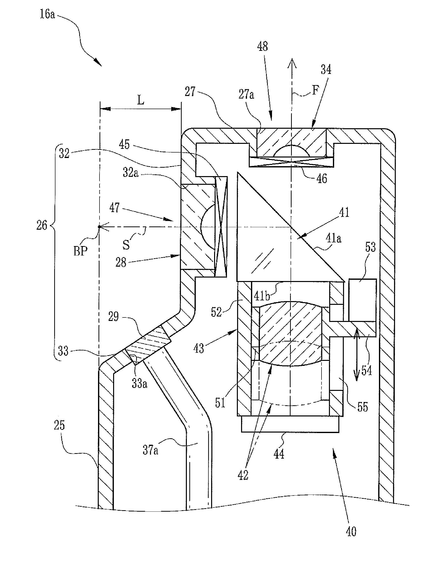
[0070]Note that, in the first embodiment, the varifocal lens 42 remains in the normal observation position (the minimum focal length) when the front-viewing observation mode is switched to the side-viewing observation mode. Alternatively, the varifocal lens 42 may be moved from the normal observation position to the magnifying observation position in response to the switching of use from the LCD panel 46 to the LCD panel 45. Thus, the normal observation is automatically switched to the magnifying observation when the front-viewing observation mode is switched to the side-viewing observation mode.

[0071]In the first embodiment, the switching between the side-viewing and front-viewing observation modes is carried out by the LCD panels 45 and 46. Alternatively, each of the side-viewing capturing optical system and the front-viewing capturing optical system may incorporate a light shielding plate and a mechanism for moving the light shielding plate to shield the light in one of the side-...

second embodiment

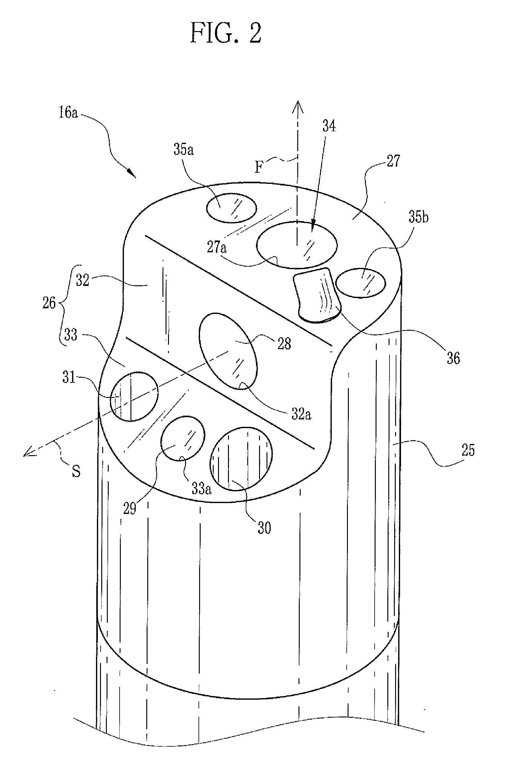
[0074]In the electronic endoscope of the second embodiment, a distal portion 80a is formed with a distal end surface 87 and a narrow portion or cutaway portion 86 having a part of an outer circumferential surface (cylindrical outer surface) 85 (in other words, a part of the distal portion 80a including the outer circumferential surface 85) cut away or removed. The distal end surface 87 is a front end surface of the distal portion 80. The cutaway portion 86 is provided with a side-viewing objective lens 88 constituting the side-viewing capturing optical system 81, and a side lighting lens 89 being the side lighting optical system. An optical axis of the side-viewing objective lens 88 extends in the side-viewing direction S.

[0075]The cutaway portion 86 is composed of the first and second surfaces 32 and 33 similar to the cutaway portion 26 of the first embodiment. The side-viewing objective lens 88 is attached to the image capture window 32a formed on the first surface 32 such that an...


PUM


Abstract

A distal portion of an electronic endoscope is formed with a cutaway portion and a distal end surface. The distal portion is provided with side-viewing and front-viewing capturing optical systems. The side-viewing capturing optical system has a side-viewing objective lens, a prism with a half mirror surface, and a varifocal lens. Light incident on the half-mirror surface from the side-viewing objective lens is reflected to be incident on a CCD through the varifocal lens. Moving the varifocal lens allows the side-viewing capturing optical system to switch from normal observation to magnifying observation and vice versa. In the magnifying observation, a best focus position resides on an extension, of an outer circumferential surface of the distal portion, facing the cutaway portion.

Description


Claims


Application Information

Patent Timeline
Owner FUJIFILM CORP
Why Eureka
Try Eureka