
Apparatus, tool, and method for modifying a portion of a floor plan based on measurements made by one or more sensors

a technology of a floor plan and a sensor, applied in the field of floor plans, can solve the problems of insufficient knowledge of the angles between all segments of the floor plan, error compensation, and inability to determine the distance between two points, etc., and achieve the effect of maximizing symmetry and improving the conformity of the floor plan

Active Publication Date: 2012-10-04
SENSOPIA
View PDF8 Cites 25 Cited by
  • Summary
  • Abstract
  • Description
  • Claims
  • Application Information

AI Technical Summary

Benefits of technology

This patent describes a system and methods for creating modifications to a floor plan based on data collected through sensors. The system includes tools designed to improve accuracy and make the floor plan fit better with pre-defined guidelines. These guidelines include things like keeping squareness among walls, avoiding intersections between walls, maintaining symmetrical relationships between walls, etc. The technical effect of this innovation is improved precision and efficiency when designing floors, reducing mistakes and simplifying construction processes.

Problems solved by technology

The patent text discusses the challenges of accurately measuring floor plans using handheld measuring devices. These devices can be affected by various factors such as the quality of the components, the operator's qualifications, and environmental conditions. These factors can lead to errors in the measurements. Additionally, the floor plan may also be influenced by scale uncertainty and imperfections in the building being measured. The technical problem addressed in the patent text is how to obtain a consistent and satisfactory floor plan based on real life measurements while compensating for measurement errors and imperfections in the building.

Method used


Image

  • Apparatus, tool, and method for modifying a portion of a floor plan based on measurements made by one or more sensors
  • Apparatus, tool, and method for modifying a portion of a floor plan based on measurements made by one or more sensors
  • Apparatus, tool, and method for modifying a portion of a floor plan based on measurements made by one or more sensors

Examples


Embodiment Construction

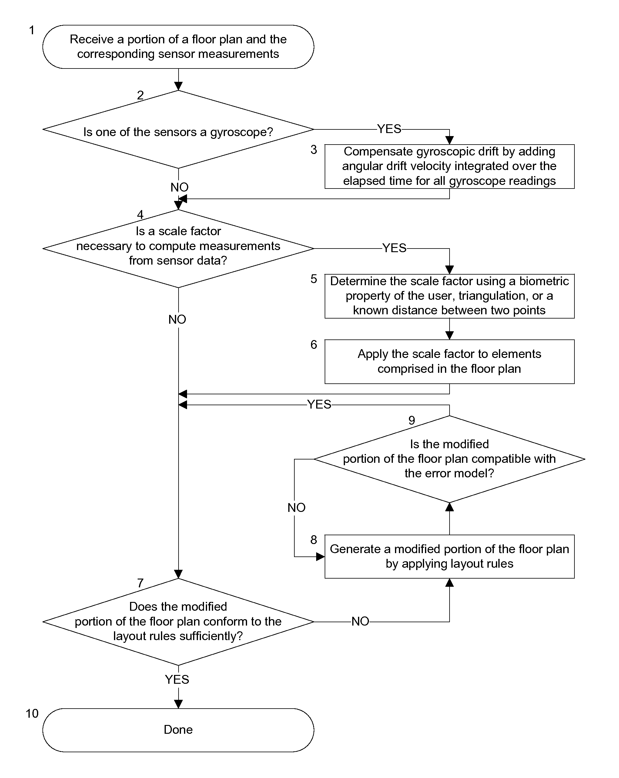
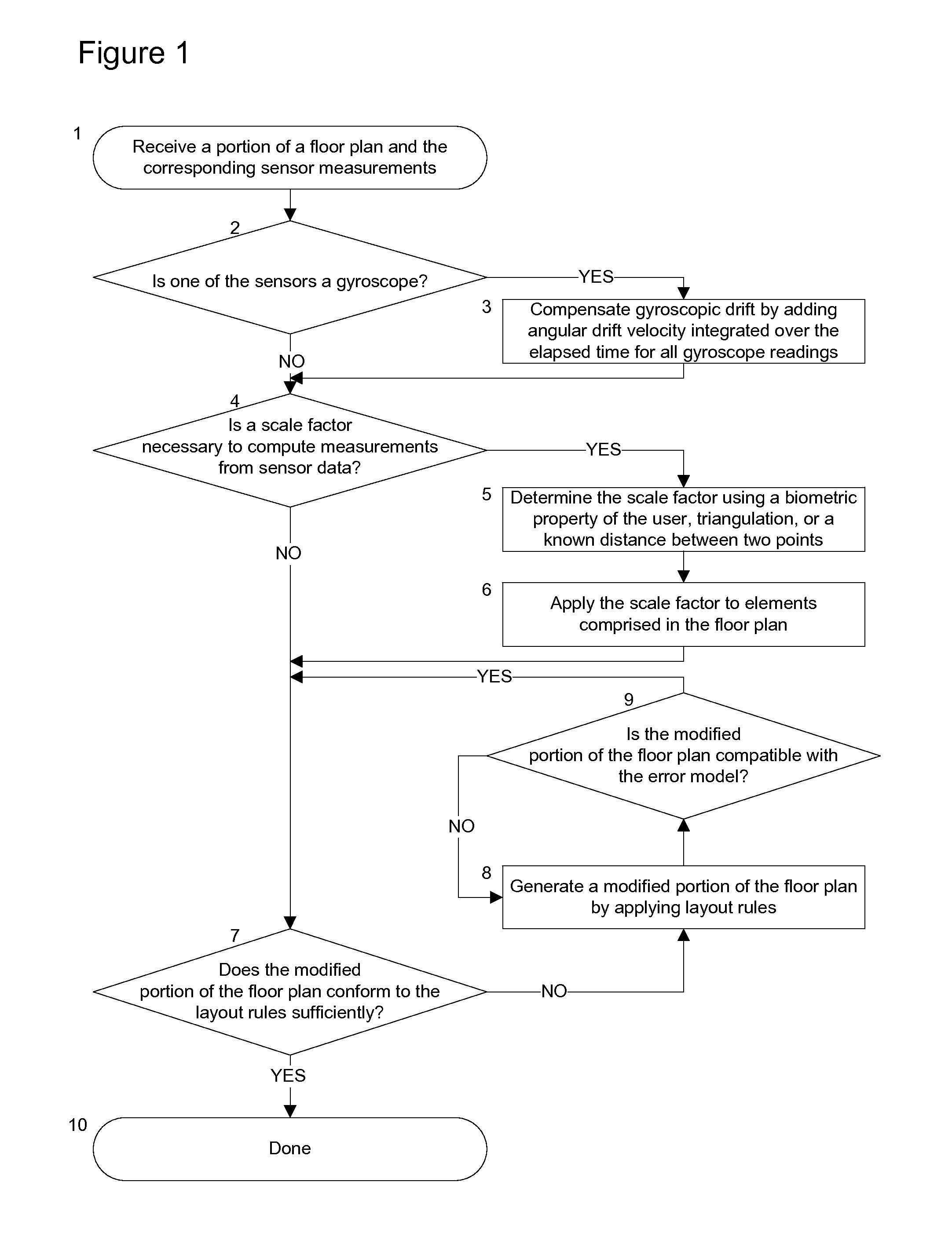
[0017]Reference is now made to FIG. 1, wherein there is shown an example of a simplified flow diagram describing the various steps of the method.

[0018]According to one of the preferred embodiments of the invention, the steps of compensating for the gyroscopic drift and for the scale factor can be performed in any order or simultaneously.

[0019]According to another preferred embodiment of the invention, the steps of verifying if the modified floor plan conforms to the layout rules 7, generating a modified floor plan 8, and verifying if the modified portion of the floor plan is compatible with the error model 9 are constrained by computation time and may be performed by any Monte Carlo algorithm that guarantees a predetermined execution time but not an optimal solution, such as a Monte Carlo method, particle swarm optimization, Newton's method, a quasi-Newton method, a gradient ascent or descent, a genetic algorithm, or simulated annealing.

[0020]According to another preferred embodimen...


PUM


Abstract

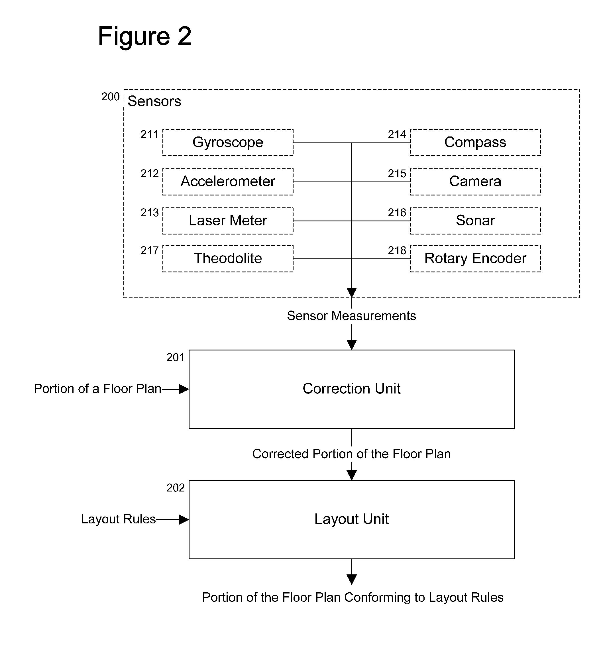
An apparatus, tool, and method for modifying a portion of a floor plan based on measurements made by one or more sensors. The apparatus comprises a correction unit for compensating the sensor measurements for instrument errors and a layout unit for improving the conformity of the portion of the floor plan to a set of layout rules. The apparatus may also comprise the sensors that made the measurements.

Description


Claims


Application Information

Patent Timeline
Owner SENSOPIA
Learn More