Pilot-operated three-position switching valve

Active Publication Date: 2012-10-11
SMC CORP
View PDF6 Cites 23 Cited by
  • Summary
  • Abstract
  • Description
  • Claims
  • Application Information

AI Technical Summary

Benefits of technology

[0019]As has been described, with the present invention, because the operation to switch the spool between the first communication state and the second communication state can be performed by applying a pilot fluid pressure to or removing the pilot fluid pressure from only one piston, the control program for the pilot valves can be simpl

Problems solved by technology

However, when the spool is switched between the first communication state and the second communication state in the above-mentioned conventional three-position switching valve, a control program for the pilot valves becomes complicated because a pilot fluid pressure needs to be applied alternately to the two pistons by alternately performing on-off control on the two solenoid-operated pilot valves.
The control program becomes complicated particularly when a plurality of switching valves are simultaneously controlled, because the number of control points increases in propo

Method used


Image

  • Pilot-operated three-position switching valve
  • Pilot-operated three-position switching valve
  • Pilot-operated three-position switching valve

Examples


Embodiment Construction

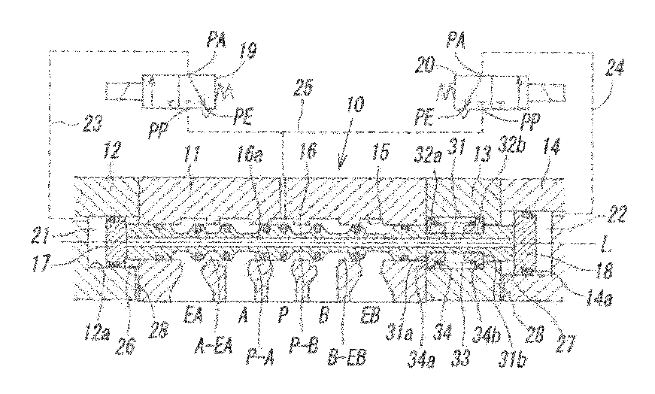
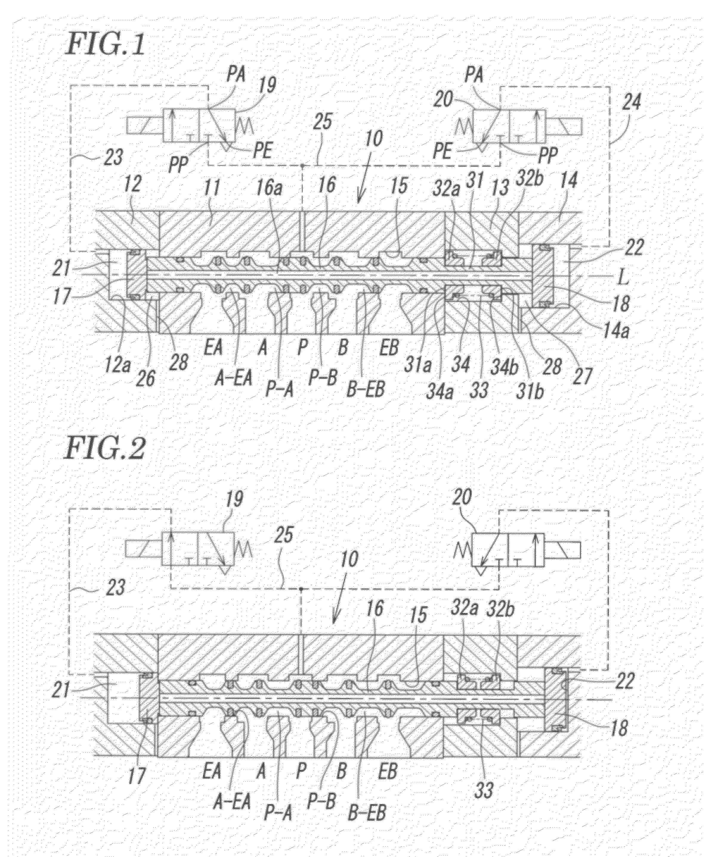
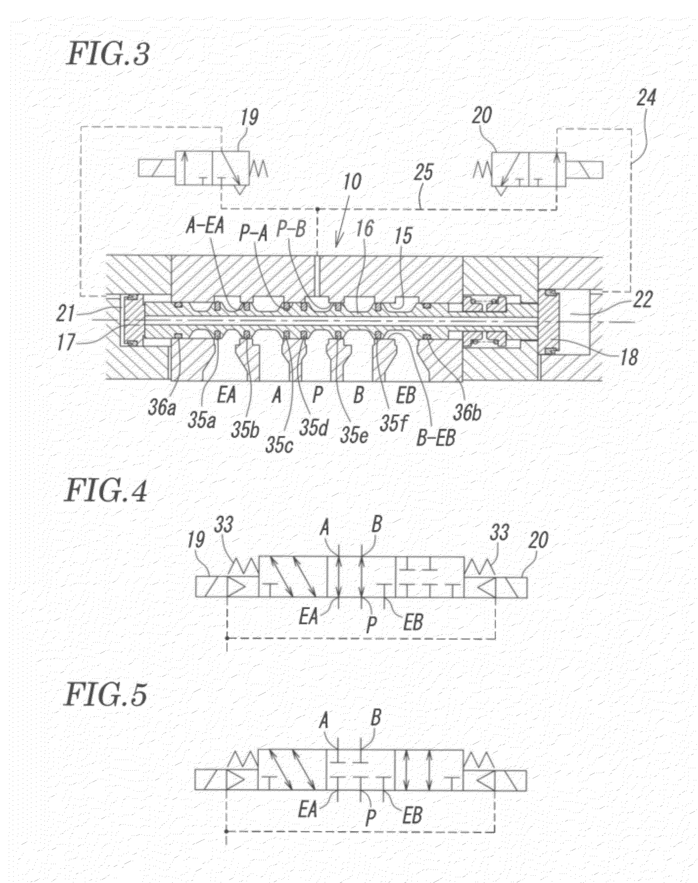
[0025]FIGS. 1 to 3 show the specific configuration of a pilot-operated three-position switching valve of the present invention, and FIG. 4 shows the symbol of this three-position switching valve. This three-position switching valve has a five-port valve configuration.

[0026]In FIGS. 1 to 3, a valve body 10 of the three-position switching valve includes a main body 11 having a plurality of ports P, A, B, EA, and EB; a first piston cover 12 connected to an end of the main body 11; and a spring cover 13 and a second piston cover 14, which are serially connected to the other end of the main body 11.

[0027]The plurality of ports include the supply port P at the center, the first output port A and the second output port B located on both sides of the supply port P, the first discharge port EA located on the first piston cover 12 side of the first output port A, and the second discharge port EB located on the second piston cover 14 side of the second output port B. These five ports are locat...


PUM


Abstract

A first piston with a smaller diameter and a second piston with a larger diameter that switch a spool between a first switching position at one end and a second switching position at the other end, and a return spring that moves the spool to a neutral switching position are provided. At the neutral switching position, some of a plurality of ports communicate with one another and the remaining ports are closed; at the first switching position, the communication-and-closure relationship of the plurality of ports is the reverse of that in the neutral switching position; and at the second switching position, all the plurality of ports are closed. When the spool is switched to the neutral switching position and the first switching position, only the first piston is operated, and when the spool is switched to the second switching position, the second piston is operated.

Description

BACKGROUND OF THE INVENTION[0001][1] Field of the Invention[0002]The present invention relates to a pilot-operated three-position switching valve in which a spool is switched between three switching positions by a pilot fluid pressure and a return spring.[0003][2] Description of the Related Art[0004]Pilot-operated three-position switching valves of this type have been known, as disclosed in, for example, Patent Literatures, Japanese Unexamined Patent Application Publication No. 59-190586 and Japanese Unexamined Patent Application Publication No. 11-182728. A known three-position switching valve is configured such that pistons are provided at both ends of a spool, which is slidably accommodated in a valve hole, a spring force of a return spring is applied the spool, the spool is moved in one direction and switched to a first switching position when a pilot fluid pressure is applied to one piston through one pilot valve, the spool is moved in the opposite direction and switched to a s...

Claims


Application Information

Patent Timeline
IPC IPC(8): F15B13/043
CPCF16K11/07F15B13/0402F15B13/0431Y10T137/0318Y10T137/86614Y10T137/8663Y10T137/8671Y10T137/87193Y10T137/87225F15B13/042F16K31/42
Inventor MIYAZOE, SHINJISENBA, KATSUYUKI
Owner SMC CORP
Why Eureka
Try Eureka