Automatic winder for inductor

A technology of inductors and winding machines, applied in the manufacture of inductors/transformers/magnets, circuits, coils, etc., can solve problems such as low efficiency, low positioning accuracy, inconvenient operation and hidden dangers, and achieve convenient adjustment of positioning angle, Simplified control program and high positioning accuracy

Active Publication Date: 2012-10-17
广东昭信智能装备有限公司
View PDF8 Cites 15 Cited by
  • Summary
  • Abstract
  • Description
  • Claims
  • Application Information

AI Technical Summary

Problems solved by technology

It can realize the full automation of the process from feeding, cutting off the thread, clamping the clamp, installing the clamp, automatic winding, unloading and discharging, and unloading the clamp. However, the machine can only roll one product at a time, and the efficiency is not high.
[0005] In addition, the positioning accuracy of the turntable of the winding machine in the prior art is generally low, the control is complicated, and the action cannot be sustained and stable, which brings a lot of inconvenience and hidden dangers to the operation

Method used


Image

  • Automatic winder for inductor
  • Automatic winder for inductor
  • Automatic winder for inductor

Examples


Embodiment 1

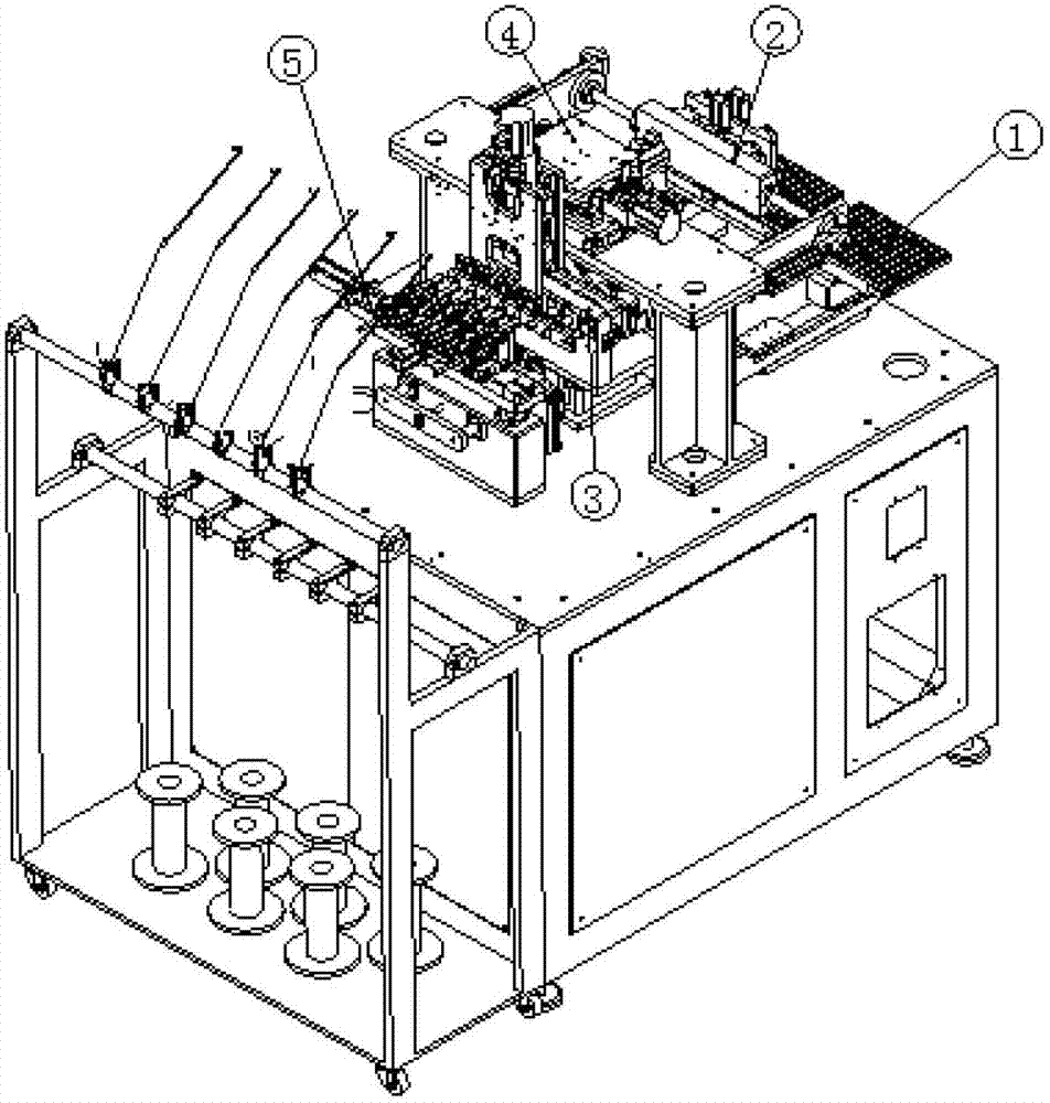
[0021] In general, figure 1 It shows the structure of the six-axis automatic winding machine for SMD inductors according to the first embodiment of the present invention. It should be noted here that although as a preferred embodiment, the six-axis automatic winding machine for SMD inductors is described in specific examples However, this is only for illustrative purposes, and the present invention is not limited thereto. It should be understood by those skilled in the art that the present invention can also be applied to such as three-axis, four-axis, five-axis, seven-axis, eight-axis In the automatic winding machine with any number of axes according to the design requirements, the automatic winding machine of the present invention is not limited to SMD inductors, but can be applied to any inductor for winding.

[0022] in such as figure 1 As shown, the six-axis automatic winding machine for SMD inductors of the present invention includes an automatic pallet unit 1, an autom...

Embodiment 2

[0037] The structure of the SMD inductor six-axis automatic winding machine of the second implementation of the present invention is as Figure 7 shown. The parts and functions of the automatic wire winding machine of this second embodiment are basically the same as those of the first embodiment, and the same units have also adopted the same reference numerals, and the difference is only in order to make the winding process Even tension control, the automatic winding machine in the second embodiment of the present invention can also preferably include winding tension control unit 6, such as Figure 8 shown.

[0038] Figure 8 Shows the winding tension control unit 6 of the SMD inductor six-axis automatic winding machine according to the second embodiment of the present invention, and the winding tension control unit 6 includes a bottom plate 58, a bracket 59, a lead plate 61, and a tensioner 62 . Among them, preferably also include wire barrel 60, and place the enameled bo...


PUM


Abstract

The invention provides an automatic winder for an inductor. According to the automatic winder, a plurality of product trays are alternately replaced on a product pick-and-place part, the operating continuity of equipment is guaranteed, and the equipment operator has enough time to replace the trays. The invention provides an automatic winder for the inductor according to one aspect of the invention; the automatic winder comprises an automatic tray unit, an automatic product pick-and-place unit, a central turntable joint unit, a three-axis interpolation conductor unit and an automatic wire clamping and shearing unit, wherein the automatic product pick-and-place unit is used for automatically picking and placing the products; the central turntable joint unit is used for picking, placing and clamping the products; the three-axis interpolation conductor unit is used for uniformly arranging enameled wires to finish winding; and the automatic wire clamping and shearing unit is used for realizing upper, lower, left, right, forward and backward motions through action of the cylinder, so that the winding action is smoothly finished.

Description

technical field [0001] The invention relates to wire winding technology, and more particularly, the invention relates to an automatic wire winding machine for radial lead inductors that wind wires on inductance elements. Background technique [0002] In the electrical and electronic industry, transformers, wire-wound resistors, inductors and other products usually require coil winding during the manufacturing process. In the past, this process was usually manually operated by workers, which not only wastes a lot of human resources, but also is inefficient. With the development of technology, the current winding work is gradually assisted by machines. [0003] In the Chinese patent CN 03214753.8 entitled "Automatic Winding Machine", a winding machine is disclosed. The automatic winding machine includes a mechanical transmission device, a signal acquisition device, an electrical control device and a display device. Among them, there is a pedal governor between the motor and ...

Claims


Application Information

Patent Timeline
Patent Type & Authority Applications(China)
IPC IPC(8): H01F41/06B65H67/06B21F11/00B65H59/00H01F41/064
Inventor 李培涛黄国文李澍郭轶夫曾涛王业辉邬嘉炜
Owner 广东昭信智能装备有限公司
Why Eureka
Try Eureka