Housing-type pipe joint

a pipe joint and housing technology, applied in the direction of flanged joints, fluid pressure sealed joints, sleeve/socket joints, etc., to achieve the effect of expanding/contraction flexibility of pipe channels

Active Publication Date: 2012-10-11
VICTAULIC OF JAPAN
View PDF3 Cites 50 Cited by
  • Summary
  • Abstract
  • Description
  • Claims
  • Application Information

AI Technical Summary

Benefits of technology

[0066]The concrete operations and effects of the inventions according to the respective claims are as described above, and according to the housing-type pipe joints of the present invention, there is commonly provided a housing-type pipe joint which couples pipes by its arc portions being bent by fastening means such as bolts and nuts so that their radii of curvature become smaller, and which enables a reduction in a fastening work, the sure confirmation of the fastening completion position, and the easy installation of the joint at an appropriate position between the pipe ends without dissembling the housing at all, thereby making a work of coupling the pipes a very simple operation, and in addition, makes it possible to surely couple and fix the pipes even when there is an error in depth of the circumferential grooves of the pipes that are to be coupled.
[0067]In addition, this housing-type pipe joint exhibits a unique effect of capable of surely coupling the both pipes even if there is an error in depth of the circumferential grooves of the pipes that are to be coupled.
[0068]Further, the housing-type pipe joint of the present invention is capable of coupling the pipe ends while sealing them in a state where the movement of the pipes trying to approach each other is restricted and a slight movement of the pipes trying to separate from each other is allowed, and accordingly, since the pipes can be coupled loosely, extension / contraction flexibility of the pipe channel can be ensured, which is suitable for the coupling of pipes buried underground which often receive an external force, for instance.
[0069]Further, there is also provided the housing-type pipe joint capable of surely coupling and fixing both pipes owing to the fixation by the convex strip portions being pressed against the far end-side walls and the near end-side walls of the circumferential grooves.

Problems solved by technology

Further, the designation of the tightening torque by the trench wrench requires a troublesome operation such as a need for preparing the trench wrench though being capable of achieving accurate fastening.

Method used


Image

  • Housing-type pipe joint
  • Housing-type pipe joint
  • Housing-type pipe joint

Examples


Embodiment Construction

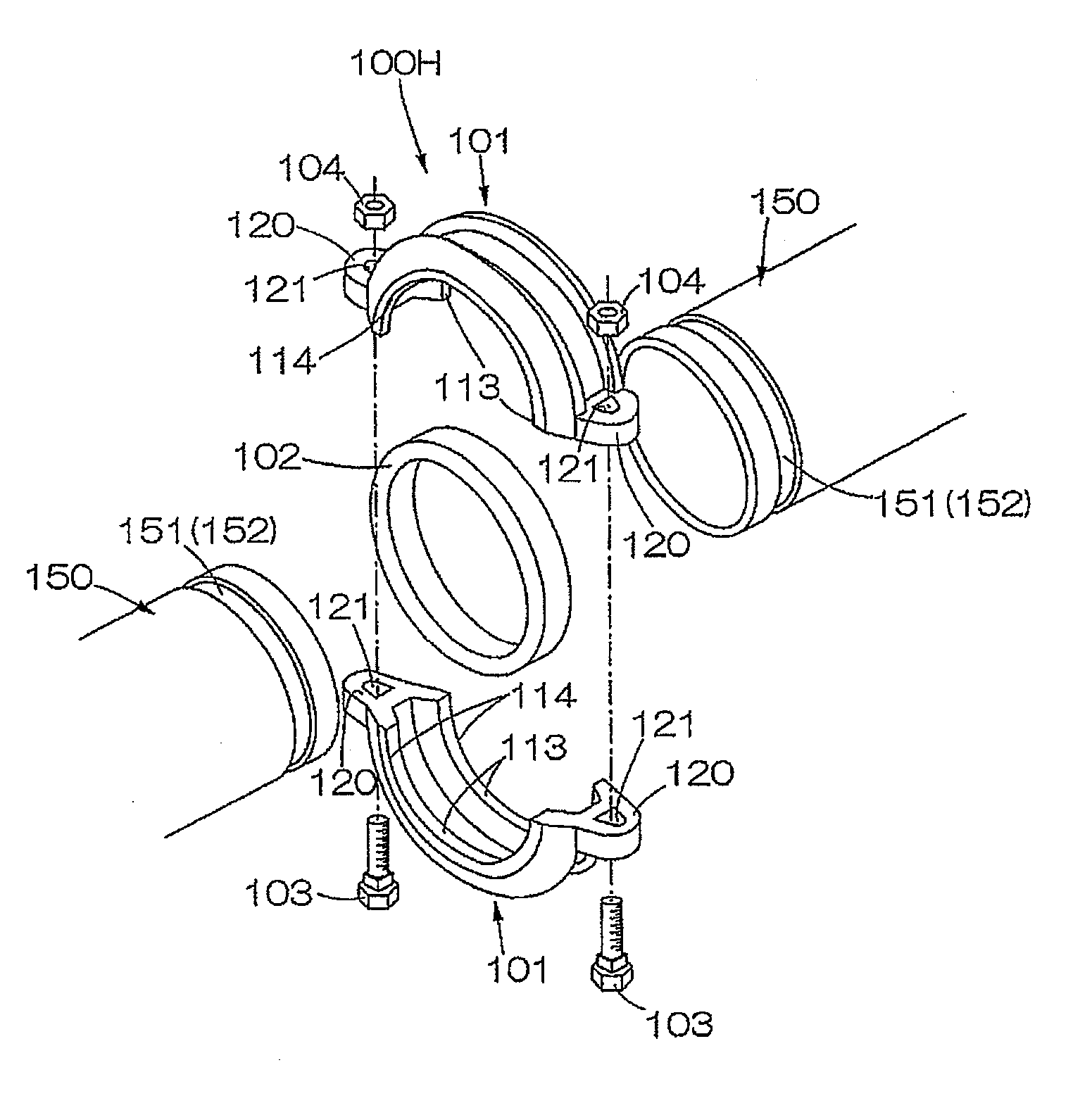
[0083]Next, an embodiment of the present invention will be hereinafter described in detail with reference to FIGS. 1 to 12, mainly about a case where pipes 50, 50 having circumferential grooves 51, 51 are coupled.

[0084]

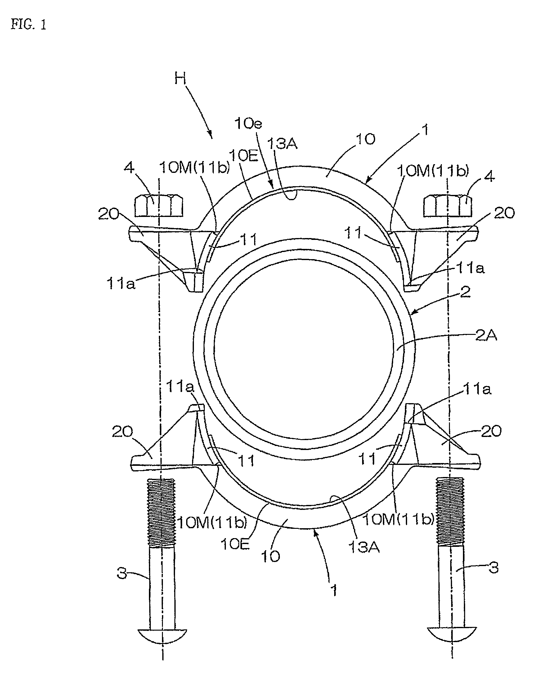
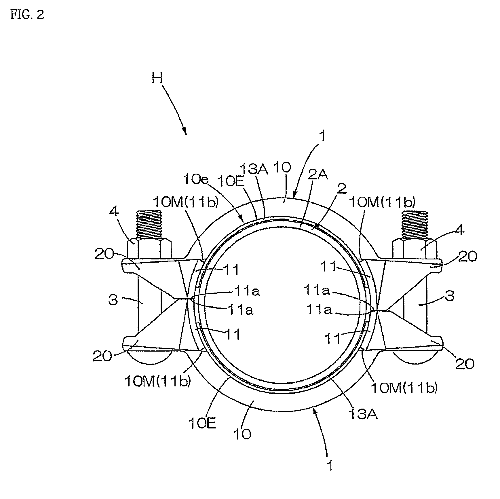
[0085]A housing-type pipe joint H of this embodiment includes a pair of joint segments 1, 1, an annular elastic seal ring 2, and bolts 3 and nuts 4 being fastening means for fastening the joint segments 1, 1. Here, the pair of joint segments 2, 2 have the same shape. Therefore, in the description of the shape, one of the joint segments 1 will be taken as an example.

[0086]The joint segment 1 has: an arc portion 10 in a substantially arc shape in which facing end portions of the pipes 50, 50 are housed; and flange portions 20, 20 extending out from both ends of the arc portion 10 respectively, and in the flange portions 20, 20, bolt insertion holes 21, 21 for having the bolts inserted therethrough are formed. The bolt insertion hole 21 is formed as an elliptic long hole...


PUM


Abstract

Provided is a housing type pipe joint to enable the confirmation of an appropriate fastening degree of a joint and reduce a load of a fastening work. The housing-type pipe joint includes a pair of joint segments, an elastic seal ring, and a fastening means fastening the pair of joint segments, in which the joint segments each have an arc portion, flange portions extending from both ends of the arc portion, a concave groove formed in an inner peripheral surface of the arc portion to have the elastic seal ring fit therein, and in which the fastening means makes the flanges of the both joint segments approach each other to make the arc portions bend so that radii of curvature of the arc portions become smaller, and when, as a result of the bending, peripheral edges of the arc portions match outer surfaces of the pipes that are to be coupled, the coupling of the pipes is completed, the housing-type pipe joint including marks on the peripheral edge regions of the arc portions, wherein, when the peripheral edges of the arc portions corresponding to the marks come into contact with the outer surfaces of the pipes, the coupling of the pipes is completed.

Description

TECHNICAL FIELD[0001]The present invention relates to a housing-type pipe joint that couples ends of pipes while sealing them.BACKGROUND ART[0002]A conventional housing-type pipe joint 100H is shown in FIG. 13. This housing-type pipe joint integrally couples two pipes in the following manner. Pipe ends of pipes 150, 150 having circumferential grooves 151, 151 in pipe end portions are set to abut on each other concentrically, an annular elastic seal ring 102 is fit around an outer side of their joint portion, thereafter a pair of substantially semi-circular joint segments 101, 101 are put is on the pipe end portions via the elastic seal ring 102 so that convex strips 113, 113 formed in inner peripheral surfaces of the joint segments 101, 101 are fit in the circumferential grooves 151, 151, and fastening means composed of bolts 103, 103 and nuts 104, 104 are screwed to bolt insertion holes 121, 121 provided in facing flange portions 120, 120 of the joint segments 101, 101.[0003]Furthe...

Claims


Application Information

Patent Timeline
Patent Type & Authority Applications(United States)
IPC IPC(8): F16L23/18
CPCF16L17/04F16L25/12F16L21/005
Inventor IKEDA, SHINTARONODA, YUJI
Owner VICTAULIC OF JAPAN
Why Eureka
Try Eureka