Unlock instant, AI-driven research and patent intelligence for your innovation.
Light-emitting element
Active Publication Date: 2012-10-11
SEMICON ENERGY LAB CO LTD
View PDF5 Cites 129 Cited by
Summary
Abstract
Description
Claims
Application Information
AI Technical Summary
This helps you quickly interpret patents by identifying the three key elements:
Problems solved by technology
Method used
Benefits of technology
Benefits of technology
[0070]In addition, in accordance with one embodiment of the present invention, the excitation energy level of an exciplex and the energy level of a guest in an excited state are set to be substantially equal, and the transition probability of the guest to an excited state is increased, whereby the probability of energy transf
Problems solved by technology
However, in general, when a phosphorescent compound is a guest and the concent
Method used
Image
Click on the blue label to locate the original text in one second.
Reading with bidirectional positioning of images and text.
Examples
embodiment 1
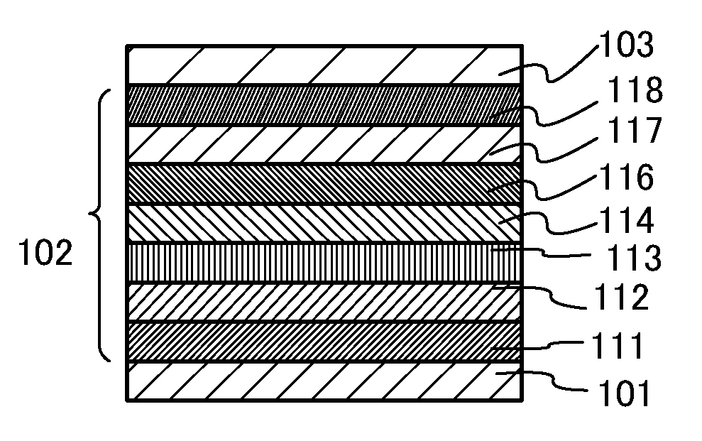
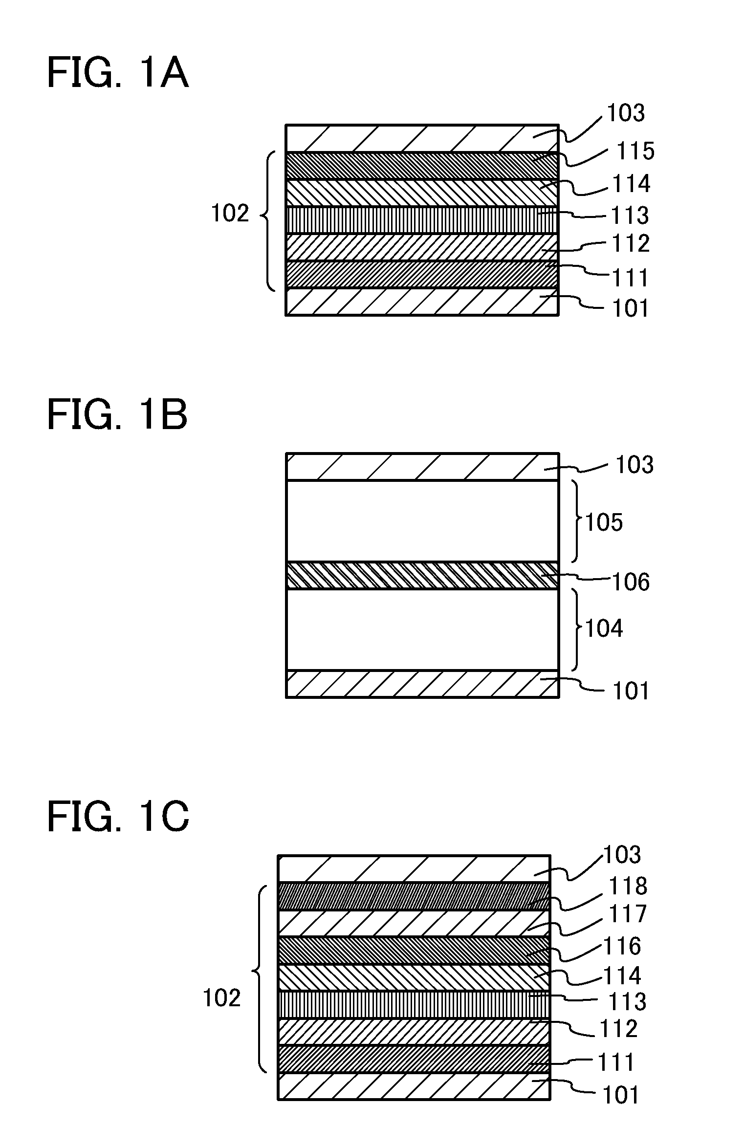
[0101]In this embodiment, a light-emitting element in accordance with one embodiment of the present invention will be described. The light-emitting element of this embodiment includes a light-emitting layer including a guest as a light-emitting substance and a host in which the guest is dispersed. Specifically, a phosphorescent compound is used as the guest and a first organic compound and a second organic compound are used as hosts. In addition, the combination of the first organic compound and the second organic compound forms an exciplex.
[0102]In this embodiment, preferably, the level of a triplet excitation energy (T* level) of each of the organic compounds used as hosts is higher than that of the guest. This is because, when the T* level of the host is lower than that of the guest, the triplet excitation energy of the guest, which is to contribute to light emission, is quenched by the host and accordingly the emission efficiency is decreased.
[0103]As described above, when the T...
example 1
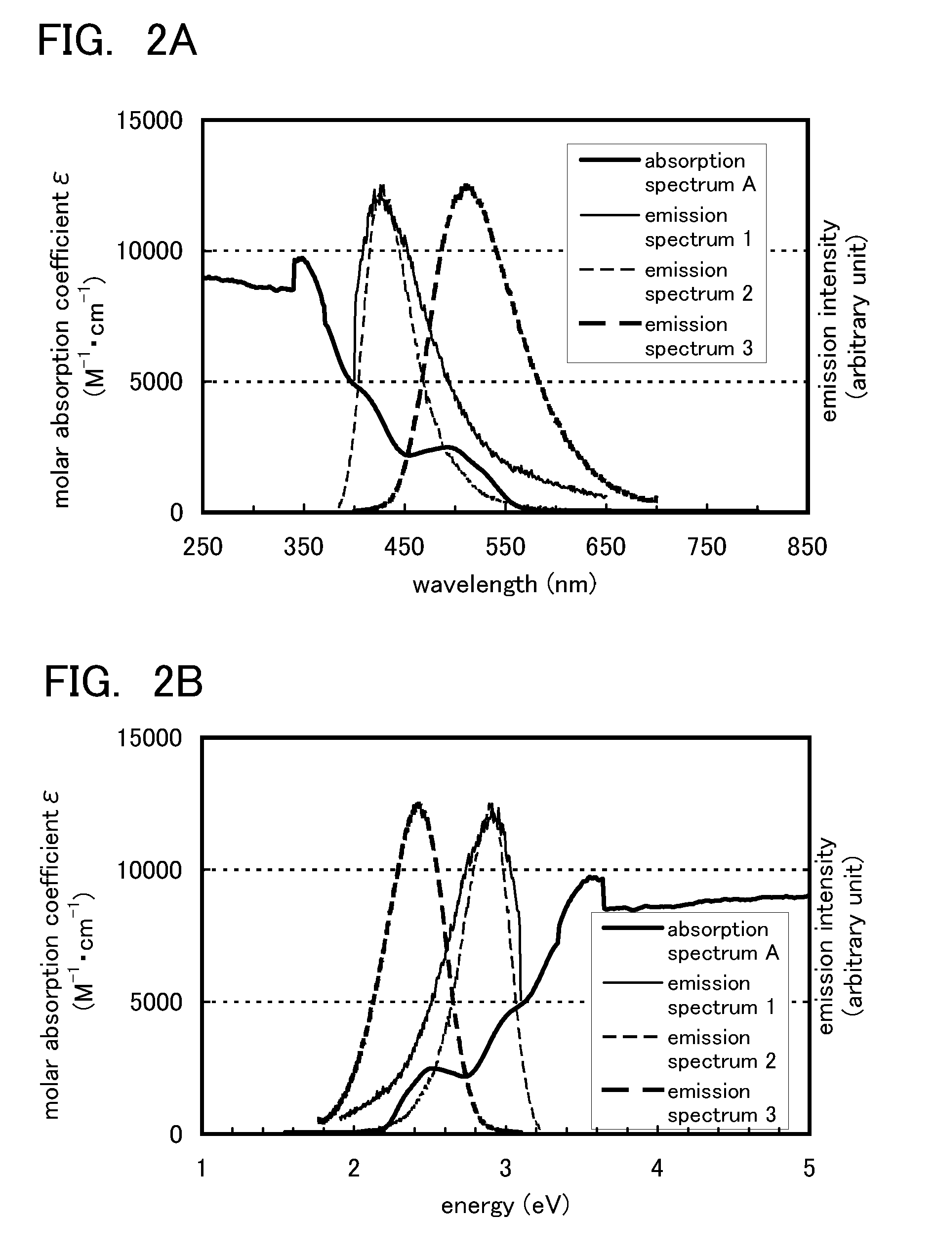
[0182]In this example, an example of a combination of a first organic compound, a second organic compound, and a phosphorescent compound which can be used for a light-emitting element in accordance with one embodiment of the present invention will be described with reference to FIGS. 2A and 2B.
[0183]The phosphorescent compound used in this example was bis(3,5-dimethyl-2-phenylpyrazinato)(dipivaloylmethanato)iridium(III) (abbreviation: [Ir(mppr-Me)2(dpm)]). The first organic compound used in this example was 2-[3-(dibenzothiophen-4-yl)phenyl]dibenzo[f,h]quinoxaline (abbreviation: 2mDBTPDBq-II). The second organic compound used in this example was 4,4′-di(1-naphthyl)-4″-(9-phenyl-9H-carbazol-3-yl)triphenylamine (abbreviation: PCBNBB). Chemical formulae of the materials described above are shown below.
[0184]FIGS. 2A and 2B each show an ultraviolet-visible absorption spectrum (absorption spectrum A) of [Ir(mppr-Me)2(dpm)] that was the phosphorescent compound, in a dichloromethane soluti...
example 2
[0190]In this example, an example of a combination of a first organic compound, a second organic compound, and a phosphorescent compound which can be used for a light-emitting element in accordance with one embodiment of the present invention will be described with reference to FIGS. 3A and 3B.
[0191]The phosphorescent compound used in this example was (acetylacetonato)bis(4,6-diphenylpyrimidinato)iridium(III) (abbreviation: [Ir(dppm)2(acac)]). The first organic compound used in this example was 2mDBTPDBq-II. The second organic compound used in this example was PCBNBB. Chemical formulae of materials used in this example are shown below. Note that the chemical formulae of the materials used in Example 1 are not shown here.
[0192]FIGS. 3A and 3B each show an ultraviolet-visible absorption spectrum (absorption spectrum B) of [Ir(dppm)2(acac)] that was the phosphorescent compound, in a dichloromethane solution. The absorption spectrum was measured with the use of an ultraviolet-visible li...
PUM
Abstract
To provide a light-emitting element with high emission efficiency or long lifetime, in which the use amount of a phosphorescent compound is small. To provide a light-emitting element including a light-emitting layer between a pair of electrodes, wherein the light-emitting layer includes a phosphorescent compound, a first organic compound, and a second organic compound, and the combination of the first organic compound and the second organic compound forms an exciplex. The light-emitting element transfers energy by utilizing the overlap between the emission spectrum of the exciplex and the absorption spectrum of the phosphorescent compound and thus has high energy transfer efficiency, even when the concentration of the phosphorescent compound is low.
Description
TECHNICAL FIELD[0001]The present invention relates to light-emitting elements utilizing organic electroluminescence (EL) (hereinafter, also referred to as organic EL elements).BACKGROUND ART[0002]Organic EL elements have been keenly studied and developed (see, Patent Documents 1 and 2 and Non-Patent Document 1). In a fundamental structure of the organic EL element, a layer containing a light-emitting organic compound (hereinafter also referred to as light-emitting layer) is interposed between a pair of electrodes. The organic EL element has attracted attentions as a next-generation flat panel display element owing to characteristics such as feasibility of being thinner and lighter, high speed response to input signals, and capability of direct current low voltage driving.[0003]In addition, a display using such a light-emitting element has a feature that it is excellent in contrast and image quality, and has a wide viewing angle. Further, since an organic EL element is a plane light ...
Claims
Application Information
Patent Timeline
Application Date:The date an application was filed.
Publication Date:The date a patent or application was officially published.
First Publication Date:The earliest publication date of a patent with the same application number.
Issue Date:Publication date of the patent grant document.
PCT Entry Date:The Entry date of PCT National Phase.
Estimated Expiry Date:The statutory expiry date of a patent right according to the Patent Law, and it is the longest term of protection that the patent right can achieve without the termination of the patent right due to other reasons(Term extension factor has been taken into account ).
Invalid Date:Actual expiry date is based on effective date or publication date of legal transaction data of invalid patent.
