Liquid ejection head and liquid ejection apparatus

a liquid ejection apparatus and liquid ejection technology, applied in printing and other directions, can solve the problems of excessive ejection of air bubbles, excessive ejection of meniscus into the pressure chamber, and broken meniscus at the nozzle, so as to improve the ability to discharge air bubbles and improve the reliability of the liquid ejection apparatus.

Active Publication Date: 2012-10-11
SEIKO EPSON CORP
View PDF4 Cites 6 Cited by
  • Summary
  • Abstract
  • Description
  • Claims
  • Application Information

AI Technical Summary

Benefits of technology

[0020]Accordingly, in addition to the fact that the pressure changes in the liquid ejection head can be absorbed by using the flexible films, it is possible to generate negative pressure in the sealed cavity that is formed between the sealing member and the

Problems solved by technology

In some cases, an excessive positive pressure or negative pressure may be created in the ink cartridge due to fluctuation of temperature or atmospheric pressure, and when such pressure is transmitted from the ink cartridge to the nozzles of the recording head, menisci formed at the nozzles may be broken.
That is, a meniscus may be excessively withdrawn into the pressure chamber from the inner rim of the nozzle, or alternatively, may outwardly expand from the nozzle opening on the ejection side.
When the pressure of the meniscus is beyond the level of pressure r

Method used


Image

  • Liquid ejection head and liquid ejection apparatus
  • Liquid ejection head and liquid ejection apparatus
  • Liquid ejection head and liquid ejection apparatus

Examples


Embodiment Construction

[0028]An embodiment of the invention will be described below with reference to the attached drawings. Although various limitations are made as preferred examples of the invention in the following embodiment, the invention is not limited thereto unless otherwise specifically described herein. In the following description, ink jet recording apparatus (hereinafter, referred to as printer) will be described as an example of a liquid ejection apparatus of the invention.

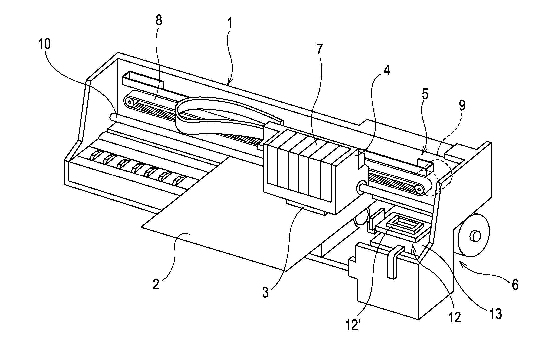
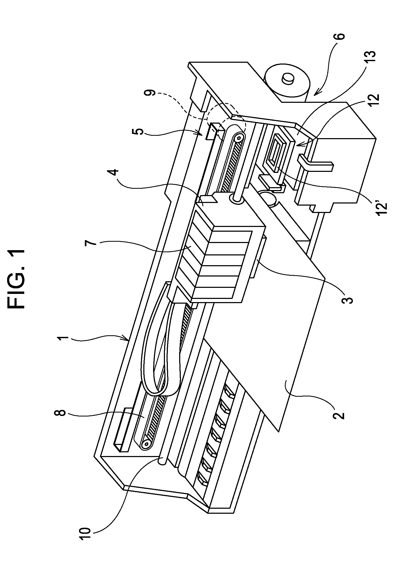
[0029]First, a schematic configuration of an ink jet recording apparatus (a type of liquid ejection apparatus; hereinafter, referred to as printer) that includes a recording head will be described below with reference to FIG. 1. The exemplified printer 1 is a device that performs recording of images and the like by ejecting ink in a liquid form onto the surface of a recording medium (ejection target) 2 such as a recording sheet. The printer 1 includes a recording head 3, a carriage 4 on which the recording head 3 is mounte...


PUM


Abstract

A liquid ejection head includes a downstream filter chamber that is disposed at an inlet opening of an ink introduction path and is provided with a filter disposed therein, and a flexible film that is disposed on an inner wall of the filter chamber at a position downstream of the filter, wherein the flexible film is configured to deform in accordance with the pressure changes in the flow channel.

Description

BACKGROUND[0001]1. Technical Field[0002]The present invention relates to a liquid ejection head such as an ink jet recording head and a liquid ejection apparatus having the same, and more specifically to a liquid ejection head that introduces a liquid from a liquid containing member into a pressure chamber and ejects the liquid from the pressure chamber through nozzles by driving a pressure generating unit, and a liquid ejection apparatus having the same.[0003]2. Related Art[0004]Liquid ejection apparatuses generally have a liquid ejection head and are configured to eject various liquid from the ejection head. Such liquid ejection apparatuses include, for example, image recording apparatuses such as an ink jet printer and an ink jet plotter. Recently, liquid ejection apparatuses are applied to various manufacturing apparatuses by taking advantage of ability to precisely eject an extremely small amount of liquid onto a predetermined position. For example, liquid ejection apparatuses ...

Claims


Application Information

Patent Timeline
IPC IPC(8): B41J2/165B41J2/175
CPCB41J2/17523B41J2/17513
Inventor KOBAYASHI, YUTAKA
Owner SEIKO EPSON CORP
Why Eureka
Try Eureka