
High Resolution Wide Field of View Digital Night Vision System

a digital night vision and wide field of view technology, applied in the field of night vision systems, can solve the problems of inconvenient installation, inconvenient maintenance, and large volume of the inertia of the inertia of the inertia of the inertia of the inertia of the inertia of the inertia of the inertia of the inertia of the inertia of the iner

Active Publication Date: 2012-10-11
VISION PROD LLC
View PDF9 Cites 43 Cited by
  • Summary
  • Abstract
  • Description
  • Claims
  • Application Information

AI Technical Summary

Benefits of technology

[0008]The present invention overcomes the limitations of the prior art by providing a wide field of view digital night vision system. The night vision system uses digital sensors in place of image intensifier tubes. The digital sensors output electronic images rather than amplified light, thereby reducing the engineering constraints of the system and allowing for features not present in existing night vision systems.

Problems solved by technology

The downside of image intensifier tubes, however, is that they are bulky and they are analog sensors.
Existing night vision systems have a number of limitations caused by the physical characteristics of image intensifier tubes.
For example, existing night vision systems have large forward projection and have forward centers of gravity, which reduces their usability.
In particular, pilots using existing systems have a restricted range of motion for their head and the forward center of gravity induces neck fatigue and is unsafe for ejection.
A non-neutral center of gravity serves to magnify the weight felt by the pilot while in the turn, which causes the night vision system to move and may result in injury to the pilot.
Existing night vision systems typically also have a limited field of view, often around 40 degrees in both the horizontal and vertical directions.
Further, they can introduce distortion in the night vision image viewed by the user at the boundary between the outputs of adjacent tubes.
There is currently no way to remove the distortion in these systems.

Method used


Image

  • High Resolution Wide Field of View Digital Night Vision System
  • High Resolution Wide Field of View Digital Night Vision System
  • High Resolution Wide Field of View Digital Night Vision System

Examples


Embodiment Construction

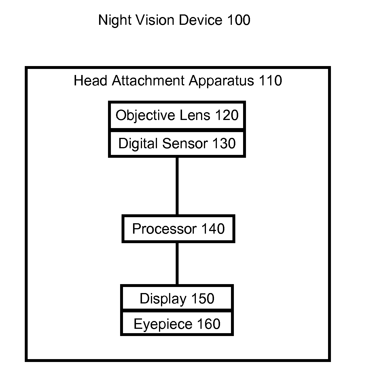
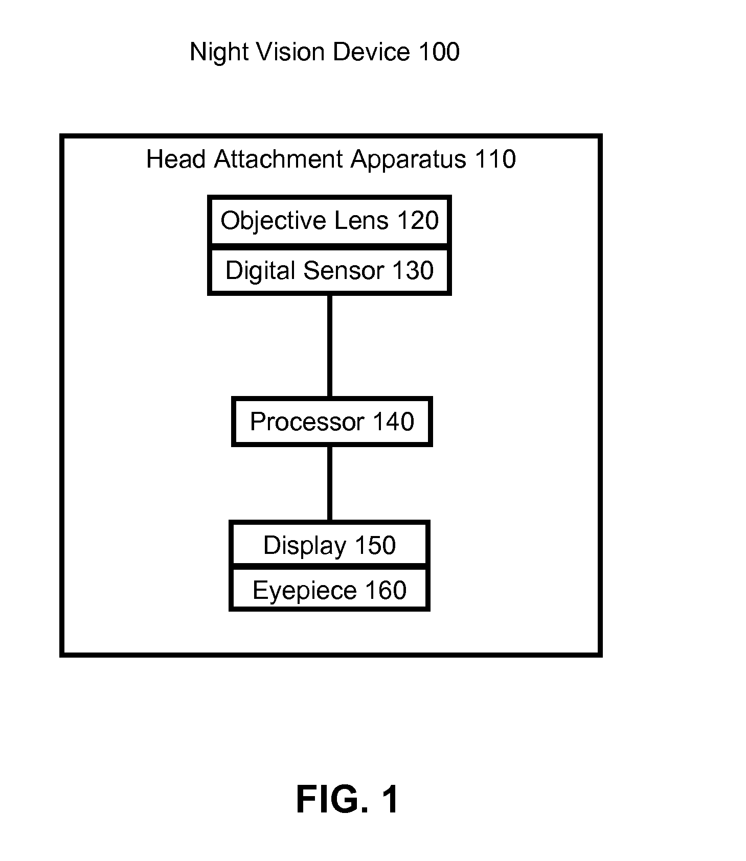
[0021]FIG. 1 is a system diagram of a night vision system. The night vision system 100 comprises a head attachment apparatus 110, an objective lens 120, a digital sensor 120, a processor 140, a display 150, and an eyepiece 160.

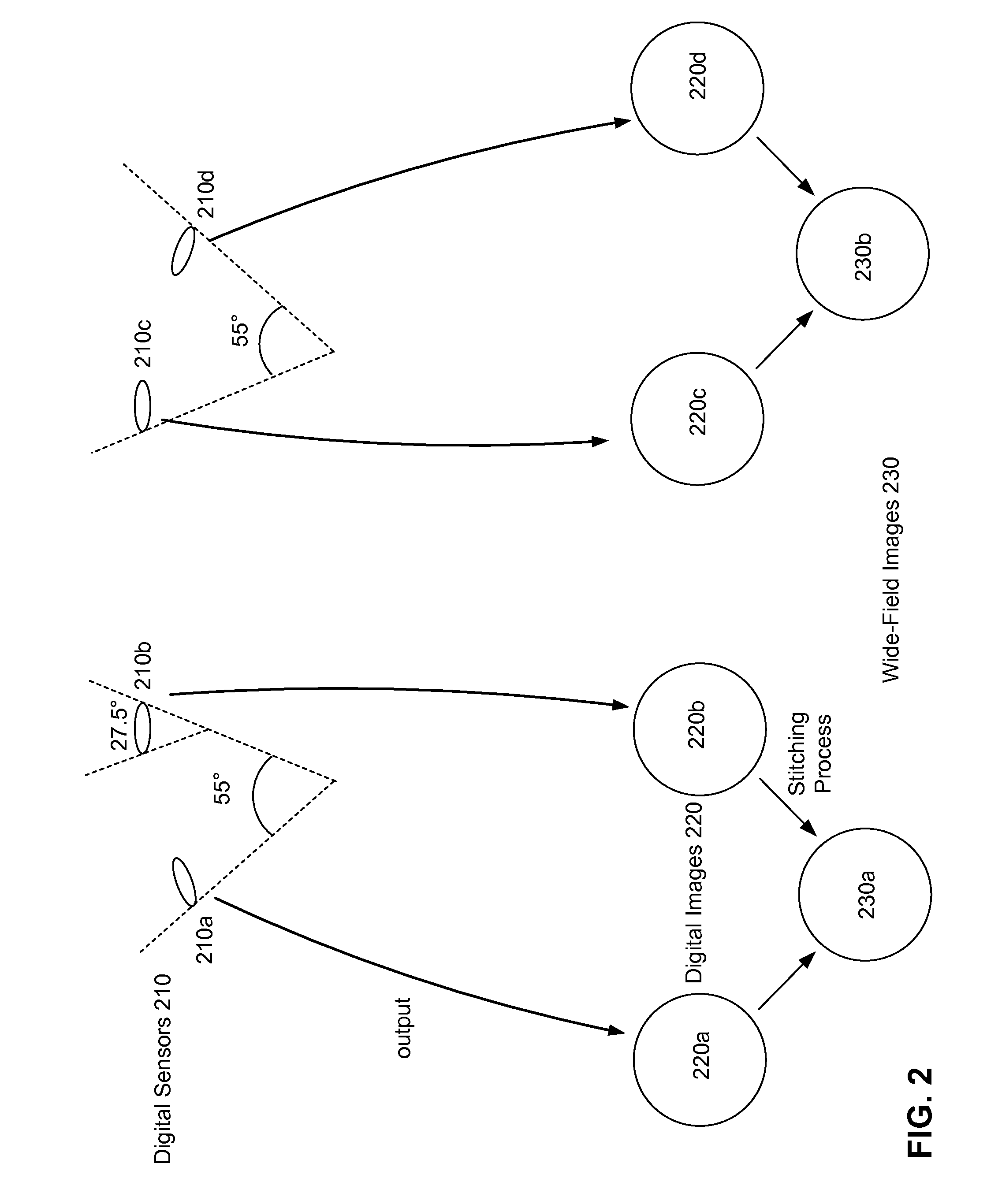
[0022]The night vision system 100 receives as input low intensity ambient light from the surroundings in the field of view of the night vision system 100 through the objective lens 120 into the digital sensor 130. The digital sensor 130 amplifies the low intensity ambient input light and outputs a digital image of the surroundings. The digital image is in an electrical format, and can be manipulated, stored, and transmitted by electronic devices such as the processor 140. The digital image is passed from the digital sensor 130 to the processor 140, which processes it to form a wide-field of view image. In one embodiment, there are multiple digital sensors 130 and the processor 140 stitches together the digital images from multiple digital sensors 130 to form a...


PUM


Abstract

A wide field of view night vision system is described. The system comprises a head attachment apparatus configured to attach to a user's head and a night vision subsystem. The night vision subsystem comprises one or more night vision image sensors attached to the head attachment apparatus. Each sensor receives input light and produces a digital image of the input light. A processor processes the digital image(s) to produce a wide-field image. The wide-field image spans at least 60 degrees of a user's horizontal field of view. A display and eyepiece attached to the head attachment apparatus receives and displays the wide-field image. The eyepiece is positionable between the display and the user's eye to image the wide-field image into the user's eye.

Description

GOVERNMENT RIGHTS LEGEND[0001]This invention was made with government support under Phase I SBIR Government contract FA8650-08-M-6892 and Phase II SBIR Government contract FA8650-09-C-6018 awarded by the United States Air Force. The government has certain rights in the invention.BACKGROUND[0002]1. Field of Art[0003]This invention generally relates to the field of night vision systems, particularly to head or helmet mounted night vision systems.[0004]2. Description of the Related Art[0005]A night vision system improves the ability of a user to see in an environment where small amounts of light are present. Existing night vision systems take in low levels of ambient light not viewable to the naked eye and amplify it to viewable levels using image intensifier tubes. An image intensifier tube functions by amplifying the number of received photons while keeping the resulting photons spatially separated so that the original image formed by the ambient light is not distorted or blurred. Th...

Claims


Application Information

Patent Timeline
IPC IPC(8): H04N7/00
CPCH04N5/2258H04N5/23238H04N5/33G02B2027/014G02B2027/0123G02B2027/011G02B2027/0138G02B27/017H04N23/45H04N23/698H04N23/21
Inventor BROWNE, MICHAEL P.
Owner VISION PROD LLC
Learn More