Method for memory mapping in a composite RFID tag facility

a memory mapping and tag facility technology, applied in the field of radio frequency id (rfid) tags, can solve the problems of low bandwidth, high failure rate of data transmission, and performance problems of current rfid tags

Active Publication Date: 2012-10-18
TEGO INC
View PDF0 Cites 41 Cited by
  • Summary
  • Abstract
  • Description
  • Claims
  • Application Information

AI Technical Summary

Problems solved by technology

However, current RFID tags suffer from performance problems.
Passive tags, while not requiring a local power source, suffer from low bandwidth and high failure rates in data transmission.
Active tags, while performing better than passive tags, are much more expensive and require a power source.

Method used


Image

  • Method for memory mapping in a composite RFID tag facility
  • Method for memory mapping in a composite RFID tag facility
  • Method for memory mapping in a composite RFID tag facility

Examples


Embodiment Construction

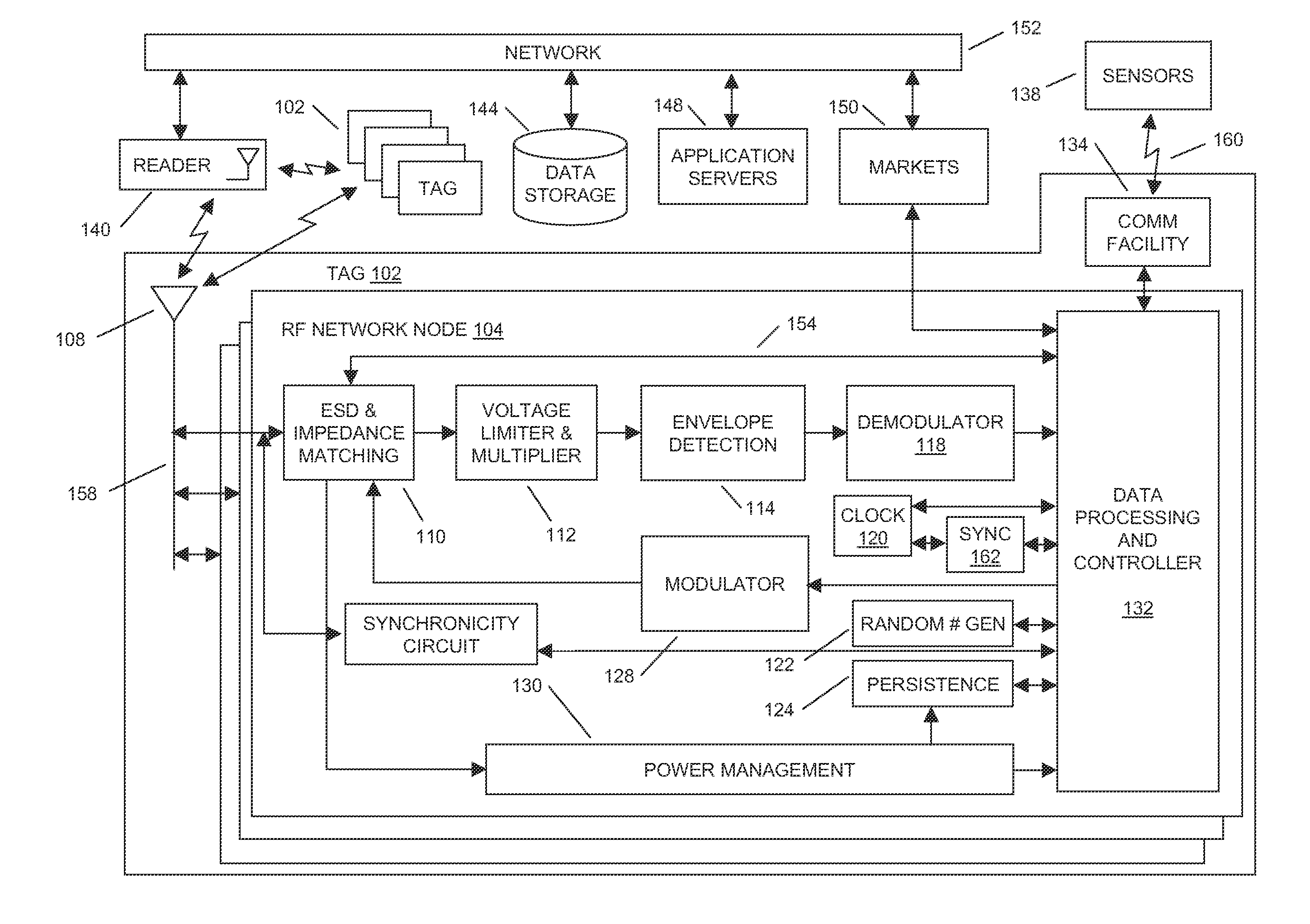
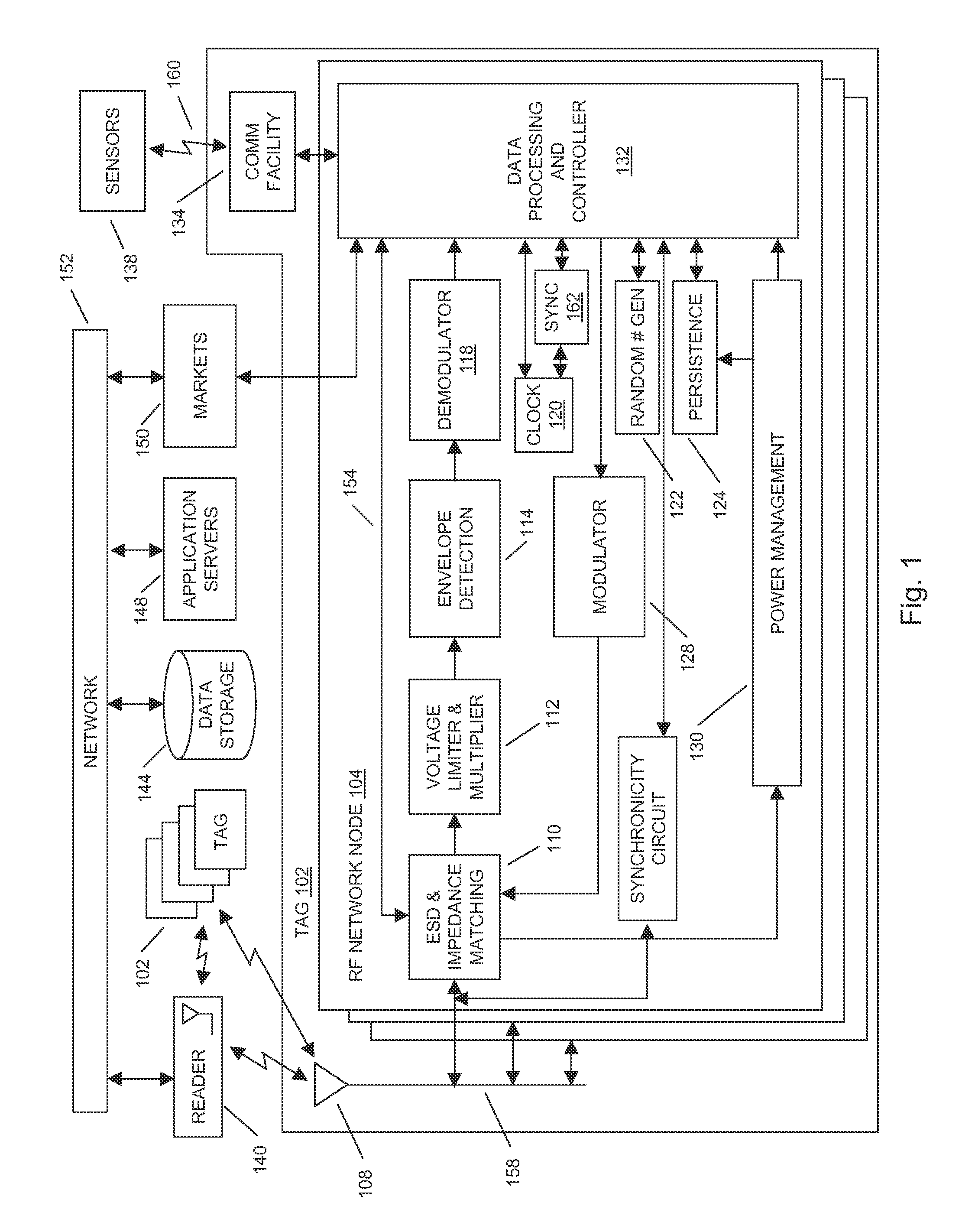
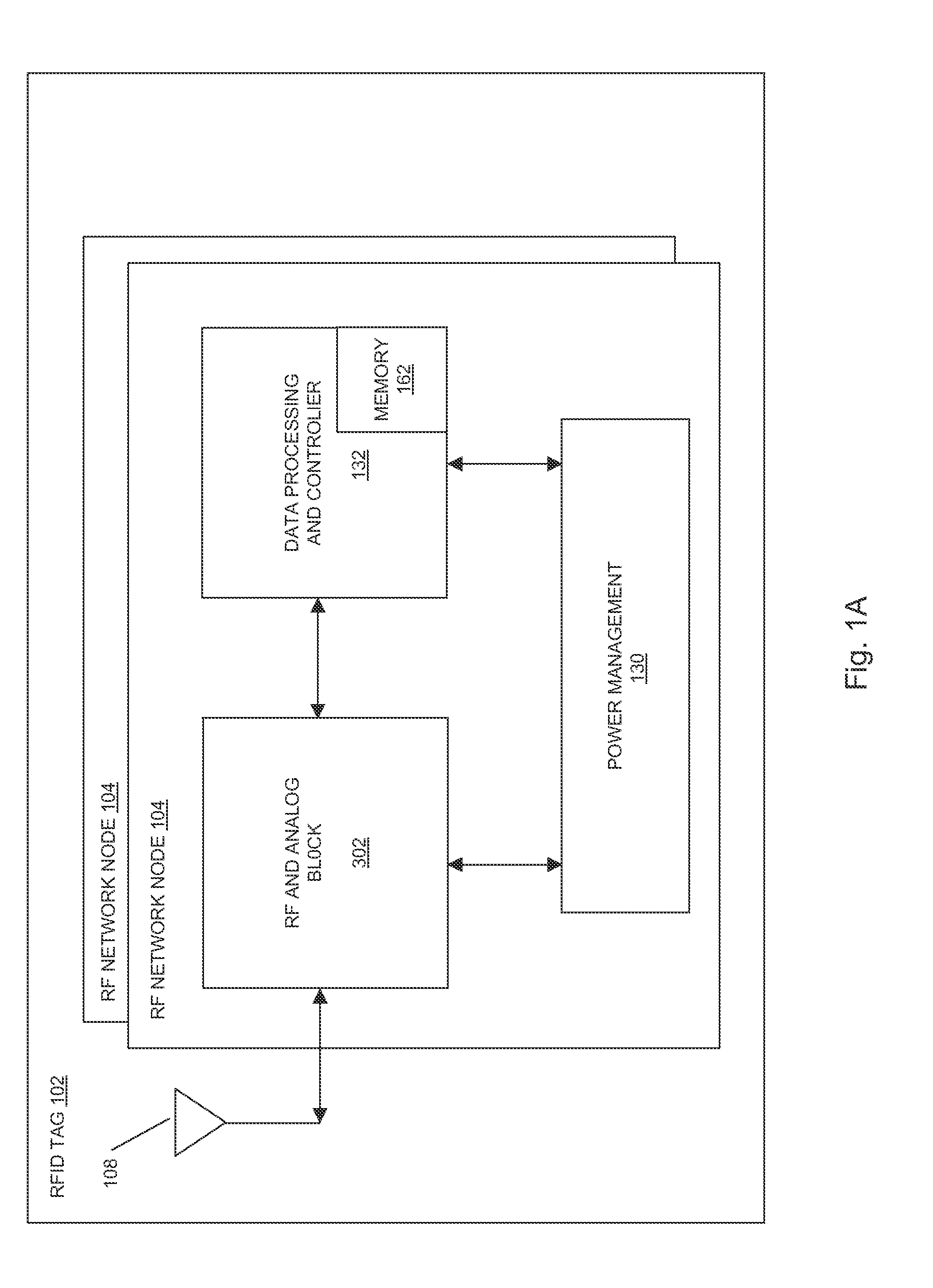
[0049]In aspects of the systems and methods described herein, a radio frequency identification (RFID) tag may use multiple RF network nodes (e.g. radio microchips) to communicate information to a RFID reader, a network, other RFID network nodes, or the like. The communication of the information may be provided to the RFID reader using at least one antenna, using a communication facility, using both the at least one antenna and the communication facility, or the like.

[0050]In aspects of the systems and methods described herein, each of the multiple RF network nodes may include radio frequency circuits, digital circuits, memory storage, communication facilities, and the like for storing and transmitting information to RFID readers, networks, other RFID tags, markets, applications, data stores, and the like. The RFID tag may include circuitry for inter RF network node communication that may provide RF network node redundancy, increased functionality, improved connectivity to the reader...


PUM


Abstract

In embodiments of the present invention improved capabilities are described for a method of memory mapping disparate memories on a composite radio frequency identification (RFID) tag, where the RFID tag includes a plurality of individual RFID devices each having a memory store with a physical memory address range and mounted to a common substrate, where at least one of the individual RFID devices comprises memory configuration information, and where a memory addressing facility maps the physical memory address ranges of each of the individual RFID devices to a single logical addressing space and presents the address space as a single memory, where the memory addressing facility is included on a computing facility separate from the composite RFID tag.

Description

CROSS-REFERENCE TO RELATED APPLICATIONS[0001]This application claims the benefit of the following provisional applications, each of which is hereby incorporated by reference in its entirety: U.S. Provisional Application No. 61 / 031,590, filed Feb. 26, 2008; and U.S. Provisional Application No. 61 / 119,595, filed Dec. 3, 2008.[0002]This application is a continuation-in-part of the following applications, each of which is hereby incorporated by reference in its entirety: U.S. application Ser. No. 11 / 609,277 filed Dec. 11, 2006; and U.S. application Ser. No. 11 / 926,033 filed Oct. 28, 2007.BACKGROUND[0003]1. Field[0004]The invention relates to Radio Frequency ID (RFID) tags.[0005]2. Description of the Related Art[0006]Radio Frequency ID (RFID) tags have been proposed as a solution for a wide range of commercial applications, including tracking of large numbers of objects in disparate locations. However, current RFID tags suffer from performance problems. Passive tags, while not requiring ...

Claims


Application Information

Patent Timeline
Patent Type & Authority Applications(United States)
IPC IPC(8): G06K19/07
CPCG06K7/0008G06Q20/352H04L67/12H04L67/04H01Q1/2216G06Q20/308G06Q20/321
Inventor MOORE, LARRYBECKHARDT, STEVEPULESTON, DAVIDHAMLIN, ROBERT W.MATS, LEONID
Owner TEGO INC
Why Eureka
Try Eureka