Reconfigurable interface-based electrical architecture

a network architecture and interface technology, applied in the field of electrical/electronic network architecture, can solve the problems of increasing the number of control units, adding a lot of cost and complexity to a vehicle, and traditional e/e network architectures lack the flexibility to gracefully handle device failures, so as to reduce the overall number of control units

Inactive Publication Date: 2012-10-18
GM GLOBAL TECH OPERATIONS LLC
View PDF7 Cites 229 Cited by
  • Summary
  • Abstract
  • Description
  • Claims
  • Application Information

AI Technical Summary

Benefits of technology

[0007]In accordance with the teachings of the present invention, an electrical network architecture including a reconfigurable interface layer is disclosed, along with a corresponding reconfiguration methodology. The interface layer is comprised of multiple reconfigurable interface devices which allow a plurality of sensors and actuators to communicate with a plurality of control units. Each sensor or actuator is connected to multiple interface devices, which in turn are connected to a bus. The control units are also connected to the bus. In the event of an interface device failure, other interface devices can be reconfigured to maintain all necessary communication between sensors, actuators and control units. In the event of a control unit failure, the interface devices can be reconfigured to route sensor and actuator message traffic to a different control unit which can handle the functions of the failed control unit. The overall number of control units can also be reduced, as each control unit has flexible access to many sensors and actuators.

Problems solved by technology

The proliferation of sensors, actuators and controllers adds a lot of cost and complexity to a vehicle.
Traditional E / E network architectures lack the flexibility to gracefully handle device failures, or to adapt as needed to maximize performance or minimize overhead.
In the event of a failure of such a controller, the affected sub-system's control functions cannot be handled by another controller in the vehicle, because communication with the affected sensors and actuators is lost.
In addition, in traditional architectures, consolidation of controllers is not possible, because individual controllers typically do not have access to sensor data from other sub-systems.

Method used


Image

  • Reconfigurable interface-based electrical architecture
  • Reconfigurable interface-based electrical architecture
  • Reconfigurable interface-based electrical architecture

Examples


Embodiment Construction

[0016]The following discussion of the embodiments of the invention directed to a reconfigurable interface-based electrical architecture is merely exemplary in nature, and is in no way intended to limit the invention or its applications or uses. For example, the disclosed architecture is described in terms of automotive applications, but the architecture is equally applicable to non-automotive systems.

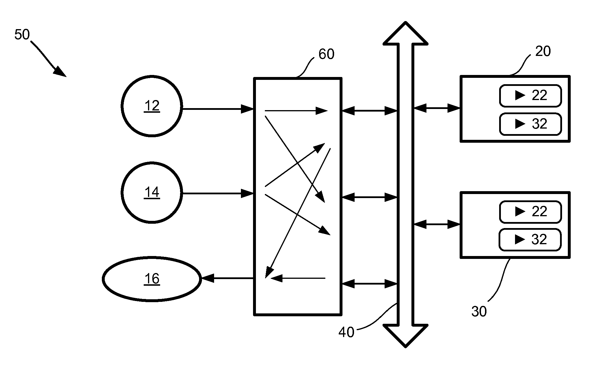
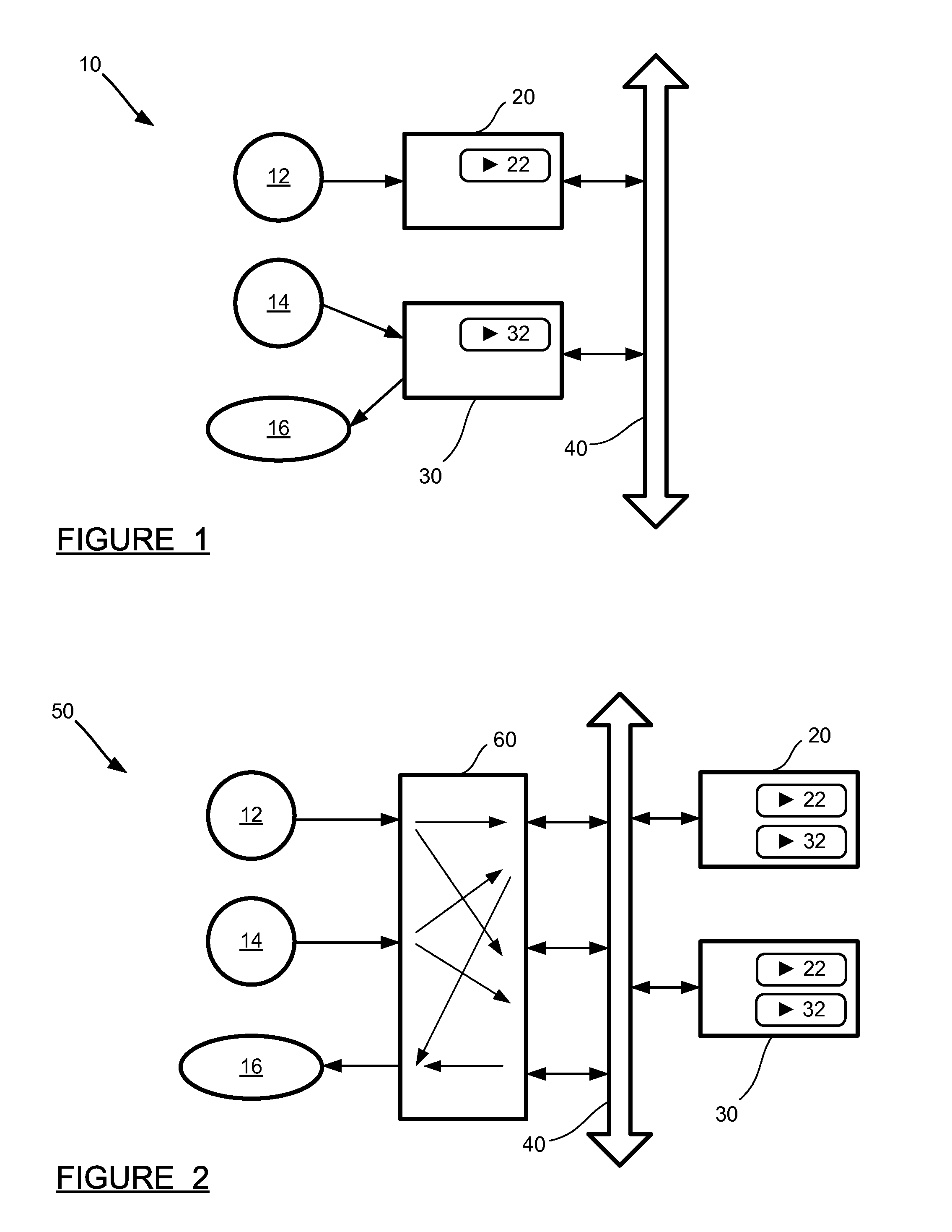
[0017]FIG. 1 is a schematic diagram of an electrical architecture 10 which is typical of those presently used in vehicles and other applications. The architecture 10 includes sensors 12 and 14, actuator 16, electronic control units (ECUs) 20 and 30, and communication bus 40. In this example, the sensor 12 is directly connected to the ECU 20, as the ECU 20 is responsible for performing a function, designated as task 22, which requires data from the sensor 12. Similarly, the sensor 14 and the actuator 16 are directly connected to the ECU 30, which handles task 32, requiring data from the ...


PUM


Abstract

An electrical network architecture including a reconfigurable interface layer, along with a corresponding reconfiguration methodology. The interface layer is comprised of reconfigurable interface devices which allow a plurality of sensors and actuators to communicate with a plurality of control units. Each sensor or actuator is connected to multiple interface devices, which in turn are connected to a bus. The control units are also connected to the bus. In the event of an interface device failure, other interface devices can be reconfigured to maintain communication between sensors, actuators and control units. In the event of a control unit failure, the interface devices can be reconfigured to route sensor and actuator message traffic to a different control unit which can handle the functions of the failed control unit. The overall number of control units can also be reduced, as each control unit has flexible access to many sensors and actuators.

Description

BACKGROUND OF THE INVENTION[0001]1. Field of the Invention[0002]This invention relates generally to an architecture for electrical networks and, more particularly, to an electrical / electronic network architecture for vehicles or other systems which uses a reconfigurable interface layer between sensors / actuators and controllers and allows messages from sensors to be dynamically routed to different controllers, thus offering an opportunity for consolidation of controllers, and providing better fault tolerance in the event of a device failure.[0003]2. Discussion of the Related Art[0004]Modern vehicles include a significant content of electrical and electronic (E / E) systems. These systems include numerous sensors, actuators and controllers which handle everything from unlocking doors to controlling the performance of the engine or suspension. The reliable operation of the E / E systems is very important, as there is often no other way to perform a function on the vehicle if a particular E...

Claims


Application Information

Patent Timeline
Patent Type & Authority Applications(United States)
IPC IPC(8): G06F1/30G06F1/26
CPCB60R16/023G05B19/042G06F13/00G06F15/025G06F13/42H04L41/0668H04L41/0695H04L12/40032H04L12/40195B60W2050/0297
Inventor DAS, DIPANKARAGRAWAL, VINOD KUMARRAJAPPAN, SEETHARAMAN
Owner GM GLOBAL TECH OPERATIONS LLC
Why Eureka
Try Eureka