Knife block and sharpener

a blade holder and knife technology, applied in the field of knives and blade holders, can solve the problems of the storage of knives' blades

Inactive Publication Date: 2012-10-25
MCPHERSONS
View PDF33 Cites 37 Cited by
  • Summary
  • Abstract
  • Description
  • Claims
  • Application Information

AI Technical Summary

Benefits of technology

The patent describes a device that has a blade that can be inserted into a housing. The device has an arm that is positioned within the opening of the housing and runs parallel to the sides of the blade. The arm has a part that engages the blade and keeps it in place. This arm can pivot between two positions, one where it engages the blade and prevents it from being pulled out, and another where it lets the blade be pulled out. The technical effect of this device is to securely hold a blade in place within a housing and allow for easy removal when needed.

Problems solved by technology

The technical problem addressed in this patent text is the potential for knives stored in existing knife blocks to fall out of their openings if the block is tilted or turned upside down, which can lead to injury. There is a need for a knife block or holder that can securely hold blades and prevent them from falling out due to tilting or overturning.

Method used


Image

  • Knife block and sharpener
  • Knife block and sharpener
  • Knife block and sharpener

Examples


Embodiment Construction

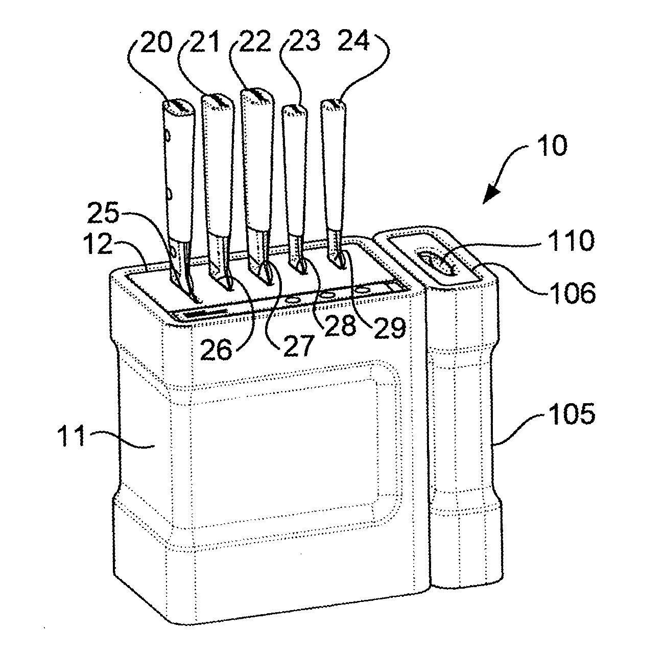
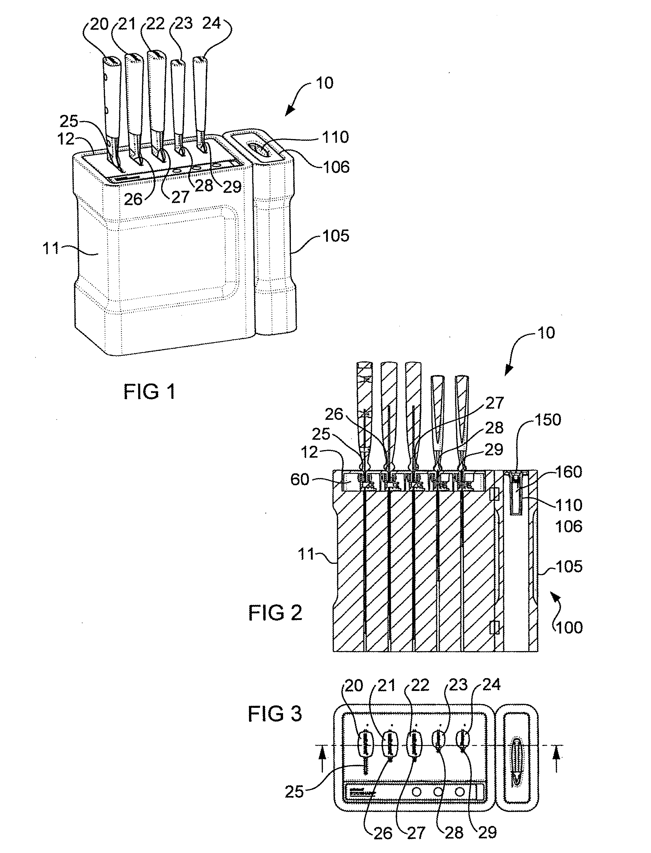
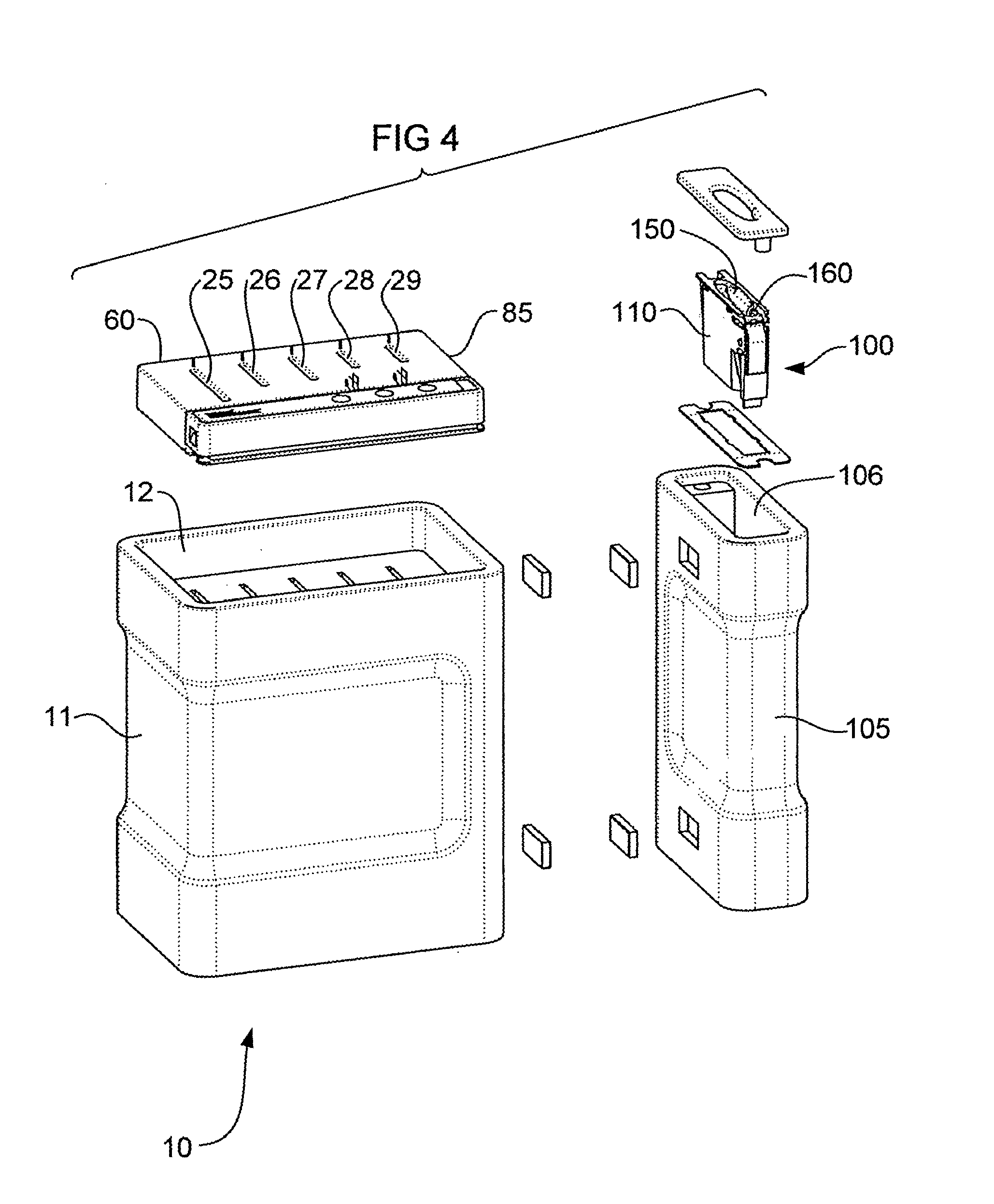
[0049]Referring to FIGS. 1 to 9, there is shown a device in accordance with an embodiment of the invention, in the form of a knife block 10, which is configured to store a plurality of knives 20, 21, 22, 23, 24 therein. Alternatively, the device may be a blade holder for storing a plurality of blades such as scissor blades, chisel blades or any other article including a blade or some other dangerous or hazardous component. The knife block 10 embodiment includes a housing 11 having a plurality of openings 25, 26, 27, 28, 29 each in the form of a longitudinal slot for receiving a respective one of the knives 20-24 therein.

[0050]As can best be seen in FIG. 8 each one of the knives 21-25 includes a blade 26 and a handle 27. The blade 26 includes a pair of elongated parallel sides 30, 31, a blunt edge 32 and a cutting edge 33 opposite the blunt edge 32. The blade 26 is connected to the handle 27 by a tang 28. The tang 28 is an integral extension of the blade 26. The blunt edge 32 and the...


PUM


Abstract

The present invention relates to a device for containing one or more blades. In a preferred for, the device is a knife block for containing a plurality of knives. The device includes a housing having a plurality of openings, each opening for containing a respective blade therein. The device also includes a blade restraining mechanism including a restraining member having active and inactive conditions in that when a blade is inserted within one of the openings such that substantially an entire cutting edge of the blade is within the opening, in the active condition the restraining member prevents withdrawal of the blade from the opening and in the inactive condition the restraining member allows withdrawal of the blade from the opening. In a preferred form, the device is configured to contain a plurality of blades that each include opposite substantially parallel sides which meet at a cutting edge, an opening within the blade extending between and transversely to the substantially parallel sides of the blade and enclosed within the blade, wherein the opening is engaged by the restraining member when in the active position to prevent withdrawal of the blade from the opening and which is disengaged by the restraining member when in the inactive position to allow withdrawal of the blade from the opening. The present invention also relates to a combination of the device and one or more of the blades.

Description


Claims


Application Information

Patent Timeline
Owner MCPHERSONS
Why Eureka
Try Eureka