Eureka AIR delivers breakthrough ideas for toughest innovation challenges, trusted by R&D personnel around the world.

Push device with clearance compensation for rack-and-pinion steering of a motor vehicle

Inactive Publication Date: 2012-10-25
JTEKT EURO
View PDF4 Cites 10 Cited by
  • Summary
  • Abstract
  • Description
  • Claims
  • Application Information

AI Technical Summary

Benefits of technology

[0012]Advantageously, the movable stop is provided with at least two toothings with staggered gear teeth, arranged on as many sectors, for example two diametrically opposite toothings each occupying a sector of 180°, and the thrust member comprises the same number of notches cooperating with those toothings, so as to stabilize the mechanism.
[0014]The off-center pusher is thus provided with a clearance compensation mechanism, which operates by “thresholds” going from one tooth to the other of the staggered gear teeth of the movable stop, which makes it possible to reduce the operating clearance. The components of this mechanism also ensure the basic operation of the off-center pusher: the thrust member is the part that transmits the thrust exerted by the compression spring to the pad, the compression spring in turn bearing against said thrust member, to generate the force that keeps the rack in contact with the pinion.

Problems solved by technology

In such a steering system, the rack-and-pinion mechanism, connected to the front wheels of the vehicle via rods, is subject to the transfer of loads, shocks and vibrations, depending on the road traveled by the vehicle.
Due to the angle formed by the rods with the rack, a load may then be produced on the rack, which risks moving it away from the pinion.
The main drawbacks of such a pusher, and the effect of increasing the withdrawal that is not offset, are a probability of the appearance of noise in case of rolling of the vehicle on a deteriorated roadway, and an increase in the bending momentum in the contact zone of the gear teeth of the pinion and the rack, in particular in case of operation at a full load.
Another drawback of this pusher device is that it requires an expensive adjustment on an assembly line.
However, the current off-center pusher devices generally do not have a robust and irreversible system, allowing, however, slight operating clearance, to absorb the clearance of the gear teeth.

Method used


Image

  • Push device with clearance compensation for rack-and-pinion steering of a motor vehicle
  • Push device with clearance compensation for rack-and-pinion steering of a motor vehicle
  • Push device with clearance compensation for rack-and-pinion steering of a motor vehicle

Examples


Embodiment Construction

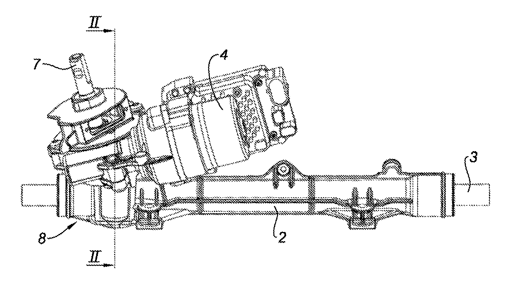
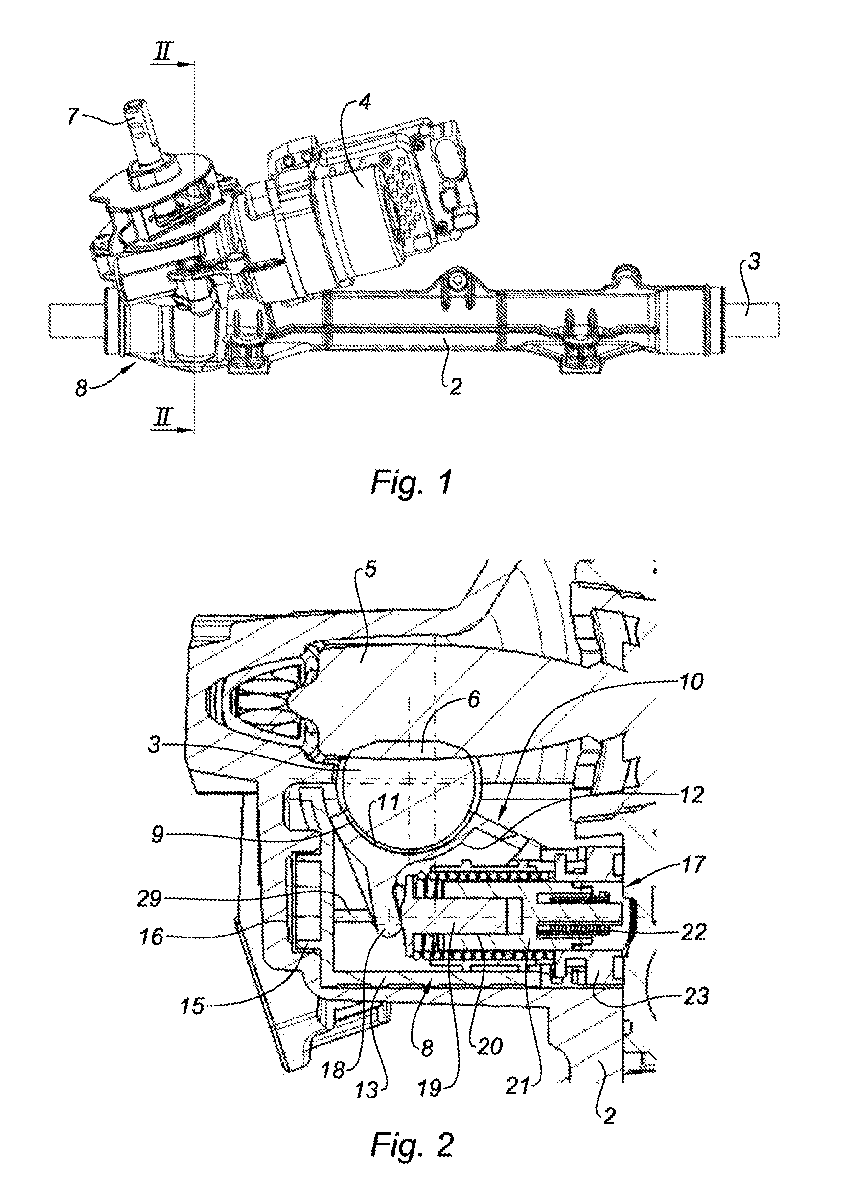
[0027]FIG. 1 shows a power-assisted steering system for a motor vehicle, with an assistance system acting at the steering pinion. The steering system comprises a steering gear-box 2, which extends along a longitudinal axis A. Slidingly mounted in the steering gear-box 2 is a rack 3, the ends of which leave the ends of the casing 2 and are coupled to tie rods (not shown here). A power assistance motor 4 is coupled, via a speed reduction gear, to a steering pinion 5 that is engaged with the toothing 6 of the rack 3 (see also FIG. 2). Reference 7 indicates the input shaft, which is connected to the steering pinion 5 and to which the steering column (not shown) is coupled, maneuvered using the steering wheel of the vehicle.

[0028]A push device, designated overall by reference 8, is provided near the steering pinion 5, to press the toothing 6 of the rack 3 against the pinion 5, the push device 8 being shown in detail in FIGS. 2 and following.

[0029]The push device 8 is placed on the rear s...


PUM


Abstract

The invention relates to a push device (8) which includes a rotary pad (10) in which the inner periphery (11) is off-centre relative to the outer periphery (12) and applied to the rear (9) of the rack (3) which is thereby pushed towards the teeth of the steering pinion (5). A clearance compensation mechanism (17) includes a thrust member (19) pressed against a radial arm (18) of the pad (10) by a compression spring (20) inserted between said member and an element (23) secured to the support (13) of the pad (10). A mobile stop (21) rotatably mounted relative to the element (23) comprises toothings having staggered gear teeth cooperating with notches of the thrust member (19). The stop (21) is connected to the element (23) by means of a torsion spring (22). The notches successively cooperate with the staggered teeth.

Description

TECHNICAL FIELD[0001]The present invention generally relates to rack-and-pinion steering for motor vehicles. More particularly, this invention relates to the so-called “push line” device, or more simply a “pusher” for such steering, the function of which is to keep the rack meshing with the steering pinion while offsetting the toothing defects, this device also serving to facilitate the mounting of the pinion in the casing of the rack-and-pinion steering system. Also more particularly, the invention relates to a so-called “off-center” pusher, which is provided with a system for automatically compensating for the clearance between the pinion and the rack.BRIEF SUMMARY OF RELATED ART[0002]In a motor vehicle rack-and-pinion steering system, a steering pinion is rotatably connected to a steering column, maneuvered using the steering wheel of the vehicle, often with the help of a hydraulic or electric assistance system. The steering pinion is engaged with a rack, slidingly mounted in the...

Claims


Application Information

Patent Timeline
IPC IPC(8): F16H55/28
CPCB62D3/123F16H55/283Y10T74/18088Y10T74/19623Y10T74/1967
Inventor BROCHOT, PATRICEREY, LAURENT
Owner JTEKT EURO
Why Eureka
Eureka Blog
Learn More