Eureka AIR delivers breakthrough ideas for toughest innovation challenges, trusted by R&D personnel around the world.

Wind powered battery charging system for electric vehicles

Inactive Publication Date: 2016-09-29
HAKEEM ABDUL +1
View PDF62 Cites 4 Cited by
  • Summary
  • Abstract
  • Description
  • Claims
  • Application Information

AI Technical Summary

Benefits of technology

The patent text describes a device called a flywheel that is connected to a turbine. The flywheel stores excess energy from the turbine when the turbine produces too much energy, and it releases this energy when the turbine produces too little energy. This allows the turbine to keep rotating and maintain smooth rotation, which results in a more stable and continuous current flow for the generator and the production of electricity.

Problems solved by technology

Travel distance for electrically powered vehicle is considerably short that requires the batteries to be recharged.
Battery currently available charging system for electrically powered vehicles is significantly less efficient than the gasoline powered vehicles.
Additionally, charging battery usually takes several hours, and the vehicle must remain inoperative.
These prior arts, however, are not adapted to generate electricity when the wind or air flow is insufficient for the generator to produce adequate electrical energy for charging batteries.

Method used


Image

  • Wind powered battery charging system for electric vehicles
  • Wind powered battery charging system for electric vehicles
  • Wind powered battery charging system for electric vehicles

Examples


Embodiment Construction

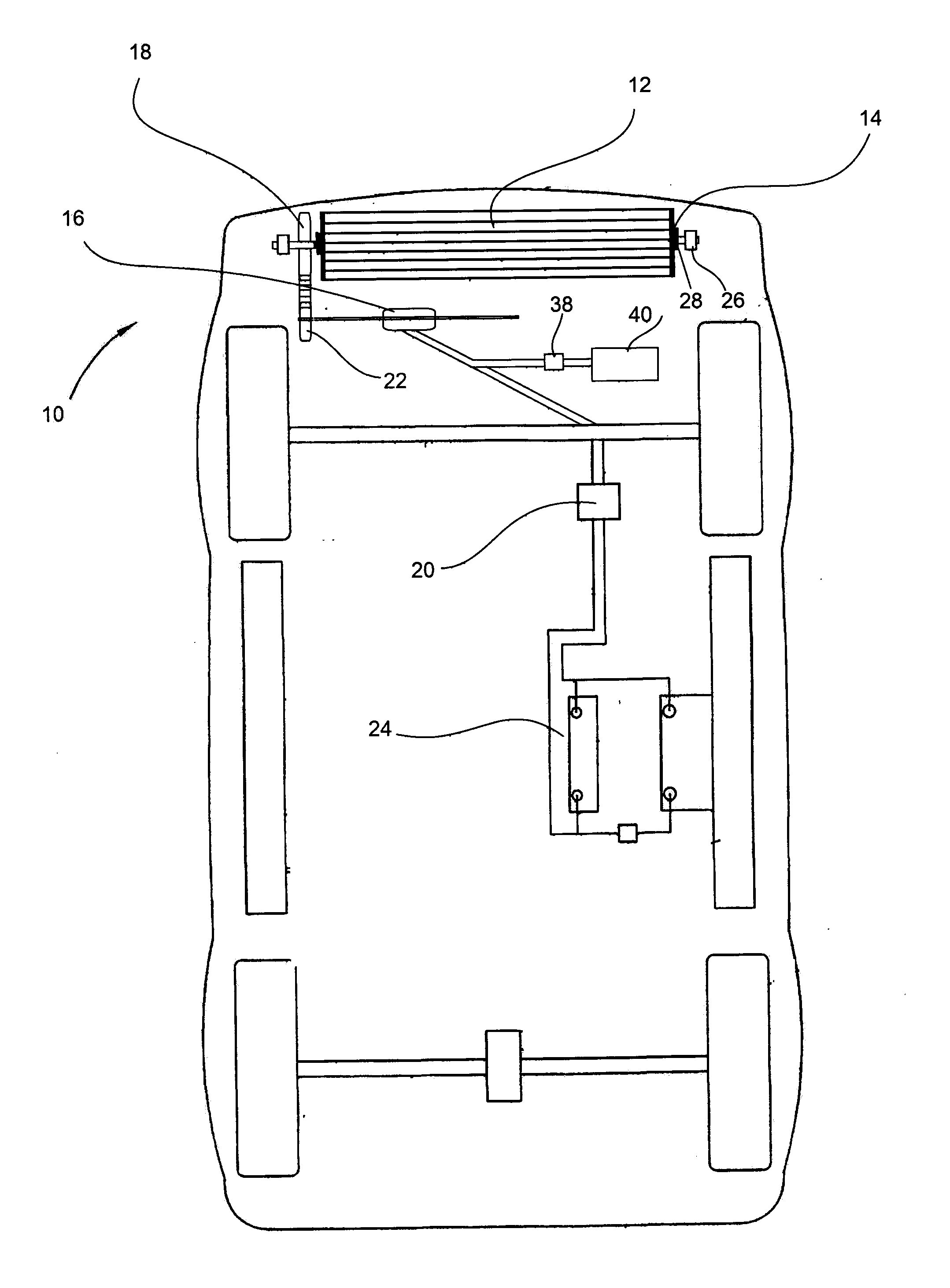
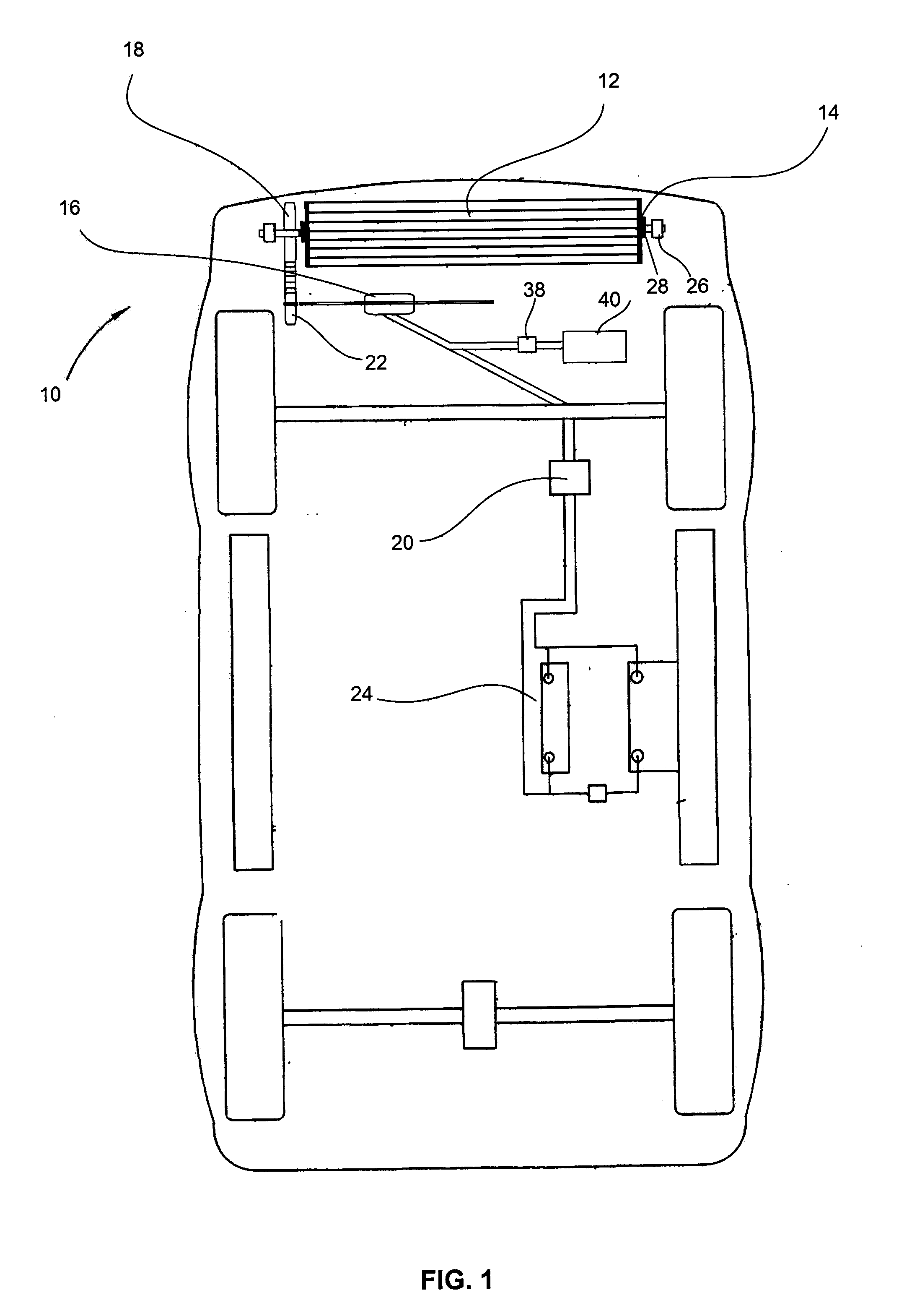
[0019]FIG. 1 shows a cutaway view of a vehicle 10 is shown. The vehicle 10 has a turbine 12, flywheels 14 rotatively engaged the turbine 12, and a turbine gear 18 operatively engaged with a lower gear 22. This lower gear 22 drives the generator 16 via a shaft to produce electricity which is used for charging batteries 24. The electricity produced by the generator 16 is also supplied to the to the AC motor 40 via the inverter 38 which converts the electric current to alternating current. If the vehicle can be powered with DC motor, the current for DC motor is supplied directly from the generator. Inverter is therefore not needed.

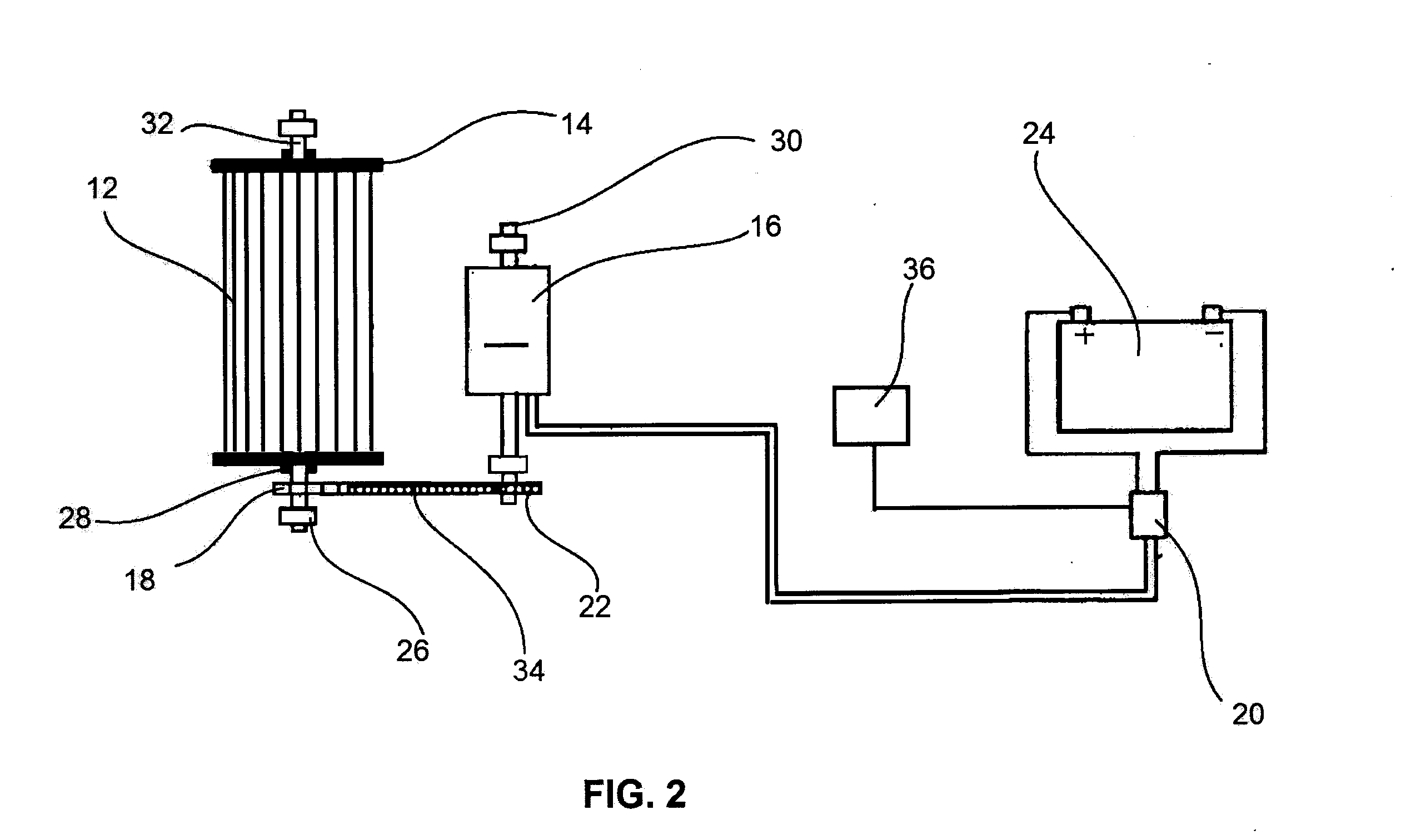
[0020]FIG. 2 shows an elevational view of the turbine 12, generator 16, flywheels 14, and batteries 24 according to an embodiment of the present invention. Still referring to FIG. 2, the turbine 12 operatively connected to a turbine shaft 32 rotates about a horizontal axis, which passes through the surfaces of turbine chamber 26 and is supported by bearing bl...


PUM


Abstract

A wind-powered system for charging batteries in an electric vehicle when the vehicle is moving at insufficient speed for a turbine to drive the generator or when the wind is insufficient to rotate the turbine. The turbine rotates about a horizontal axis and is rotatably engaged with flywheels, wherein the flywheels store mechanical energy while the vehicle is moving at a high speed. A control device receives input signals from an electric charge sensor and determines electric current produced by the generator to release mechanical energy from the flywheels to the turbine for driving the generator. The generator produces electricity which is stored on the batteries for the use of the vehicle.

Description

CROSS-REFERENCE TO RELATED APPLICATION[0001]The present application is based on, and claims the benefit of priority of U.S. application Ser. No. 62 / 136,628, filed on Mar. 23, 2015, the disclosure of which is hereby incorporated by reference herein in its entirety.BACKGROUND OF THE INVENTION[0002]1. Field of the Invention[0003]The field of the invention is related to a system for generating electricity in an electric vehicle powered by a turbine and a generator for charging batteries when the vehicle is moving at insufficient speed for a turbine to drive the generator or when the wind is insufficient to rotate the turbine. The invention also relates to a control device to determine the electric charge produced by the generator for charging the batteries. The flywheels store the mechanical energy when the turbine rotates at a high speed and releases the energy at the low speed to maintain the momentum of the turbine when the wind or air flow is insufficient to rotate the turbine, and ...

Claims


Application Information

Patent Timeline
IPC IPC(8): F03D9/12F03D9/25F03D7/06F03D9/00F03D3/00F03D3/04
CPCF03D9/12F03D3/002F03D9/25F03D7/06F03D9/002F03D3/04B60K16/00F03D9/32Y02E10/728Y02E10/74Y02E60/16Y02E70/30F03D9/11F03D15/10F03D80/82
Inventor HAKEEM, ABDULSAMEER, AETIZAZ
Owner HAKEEM ABDUL
Why Eureka
Eureka Blog
Learn More