Eureka AIR delivers breakthrough ideas for toughest innovation challenges, trusted by R&D personnel around the world.

Reduced noise jet engine

Active Publication Date: 2006-05-18
THE BOEING CO
View PDF14 Cites 43 Cited by
  • Summary
  • Abstract
  • Description
  • Claims
  • Application Information

AI Technical Summary

Benefits of technology

[0005] The above limitations are overcome by a noise reduction system in accordance with preferred embodiments of the present invention. In one preferred form the noise reduction system comprises a plurality of exhaust mixing tabs spaced apart from one another and extending from a lip of an exhaust nozzle of a jet engine nacelle adjacent a flow path of an exhaust flow emitted from the exhaust nozzle. Each of the exhaust mixing tabs are constructed to be controllably deformable from a first position adjacent the flow path to a second position extending into the flow

Problems solved by technology

This results in the attenuation of noise generated by the jet engine.
This causes intermixing of the exhaust flow with adjacent air flow, thereby attenuating noise generated as the exhaust flow exits the nozzle.

Method used


Image

  • Reduced noise jet engine
  • Reduced noise jet engine
  • Reduced noise jet engine

Examples


Embodiment Construction

[0016] The following description of the preferred embodiments is merely exemplary in nature and is in no way intended to limit the invention, its application or uses. Additionally, the advantages provided by the preferred embodiments, as described below, are exemplary in nature and not all preferred embodiments provide the same advantages or the same degree of advantages.

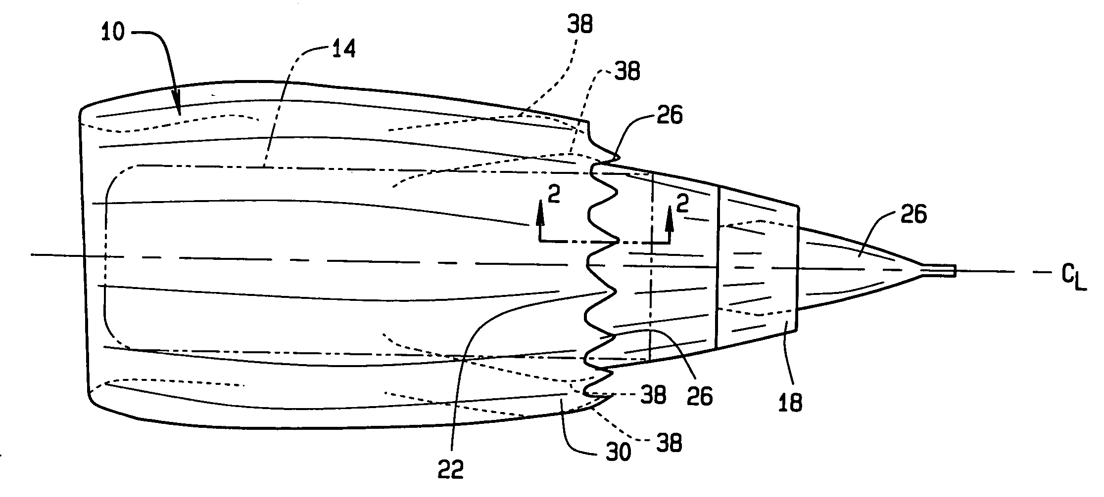
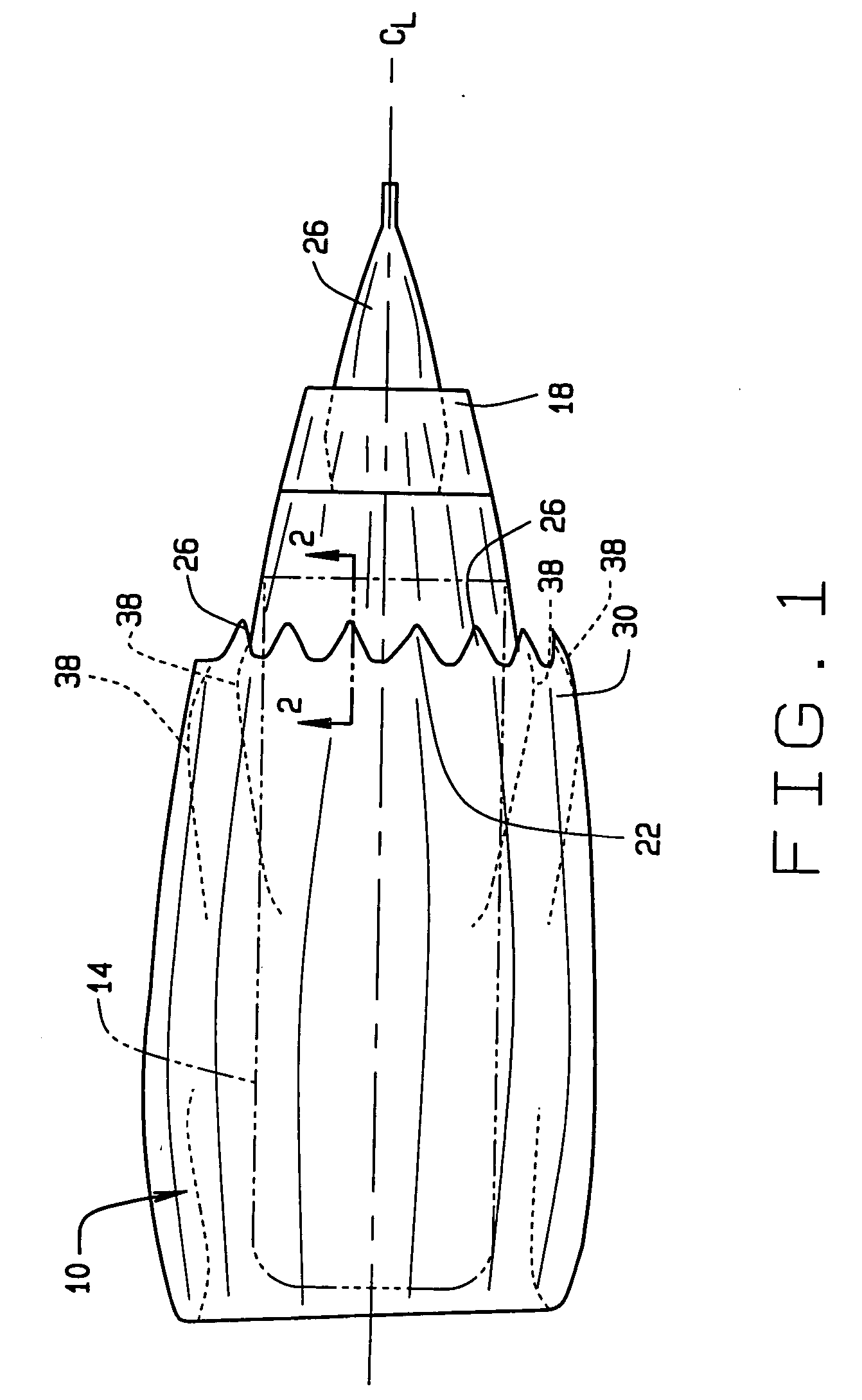
[0017] Referring to FIG. 1, there is shown an engine nacelle 10 for housing a jet engine 14. The nacelle 10 includes a primary exhaust gas flow nozzle 18, also referred to in the art as a core exhaust nozzle that channels the exhaust flow of from a turbine (not shown) of the engine 14 out the aft end of the nacelle 10. The nacelle 10 additionally includes a secondary exhaust gas flow nozzle 22, also referred to in the art as a bypass fan exhaust nozzle, that directs the exhaust flow from an engine bypass fan (not shown) out of the aft end of the nacelle 10. A plug 24 is disposed within the nacelle 10. In a preferre...


PUM


Abstract

A system for controlling a position of jet engine exhaust mixing tabs includes a plurality of exhaust mixing tabs spaced apart from one another and extending from a lip of an exhaust nozzle of a jet engine nacelle adjacent a flow path of an exhaust flow emitted from the exhaust nozzle. Each of the exhaust mixing tabs are constructed to be controllably deformable from a first position adjacent the flow path to a second position extending into the flow path of the exhaust flow in response to a control signal applied to each of the exhaust mixing tabs. In the first position, the exhaust mixing tabs either have no affect on the thrust produced, or increase the momentum (thrust) of the exhaust flow exiting from the exhaust nozzle. In the second position, that is, the “deployed” position, the exhaust mixing tabs are deformed to extend into the flow path. In this position the exhaust mixing tabs promote mixing of the exhaust flow with an adjacent air flow. This results in the attenuation of noise generated by the jet engine.

Description

FIELD OF INVENTION [0001] This invention relates to the reduction of noise produced by jet engines, and more particularly to an engine nacelle exhaust nozzle having an Irregular edge that forms a plurality of exhaust mixing tabs adapted to improve mixing of exhausts to attenuate noise produced by the engine. BACKGROUND OF THE INVENTION [0002] With present day jet aircraft, structures typically known in the industry as “chevrons” have been researched to attenuate noise generated by a jet engine. The chevrons have traditionally been fixed (i.e., immovable), triangular, tab-like elements disposed along a trailing edge of a primary and / or a secondary exhaust nozzle of the jet engine nacelle such that they project into the exhaust gas flow stream exiting from the exhaust nozzle. The chevrons have proven to be effective in reducing the broadband noise generated by the mixing of primary-secondary and secondary / ambient exhaust streams for high thrust operating conditions. Since the chevrons...

Claims


Application Information

Patent Timeline
IPC IPC(8): F02K1/38
CPCF02K1/386F02K1/44F02K1/48F05D2260/96F05D2300/505
Inventor WHITE, EDWARD V.
Owner THE BOEING CO
Why Eureka
Eureka Blog
Learn More