
Gate valve

a technology of gate valve and valve plate, which is applied in the direction of valve arrangement, slide valve, mechanical equipment, etc., to achieve the effect of simple mounting structure and stabilizing the position of the valve pla

Active Publication Date: 2012-10-25
SMC CORP
View PDF5 Cites 11 Cited by
  • Summary
  • Abstract
  • Description
  • Claims
  • Application Information

AI Technical Summary

Benefits of technology

[0010]The valve plate is desired to be fixed firmly to the valve rod in an adequate posture. However, it does not means that high-strength fixing means formed by a highly accurate processing is desired, but means that employment of means which can fix the valve plate firmly in a posture as adequate as possible within a range which allows mounting and demounting operation easily from the opening at the upper end of the valve box, which achieves easy mounting of the valve plate in a stable posture while avoiding the problem of generation of dust or the like, is required.
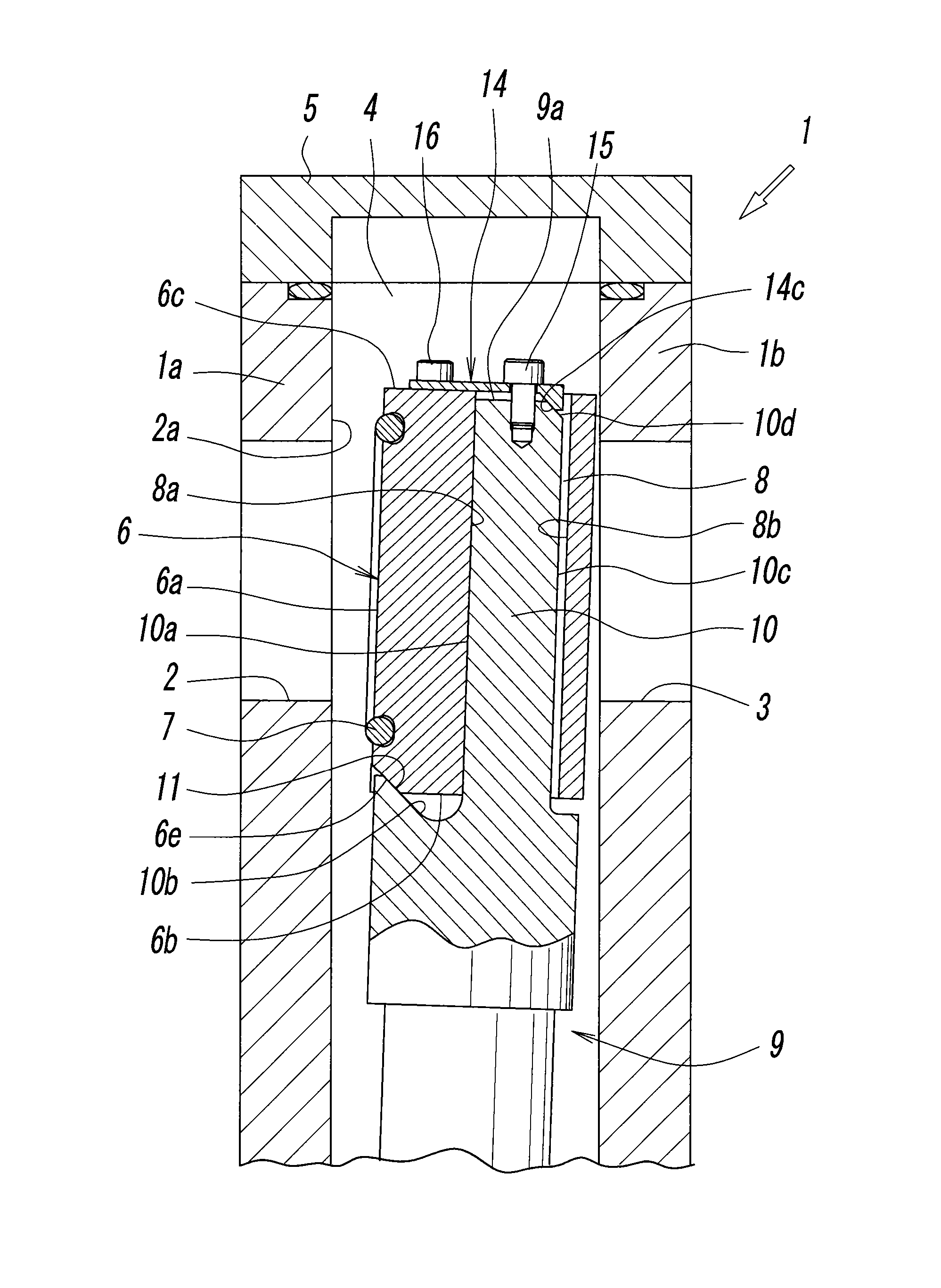
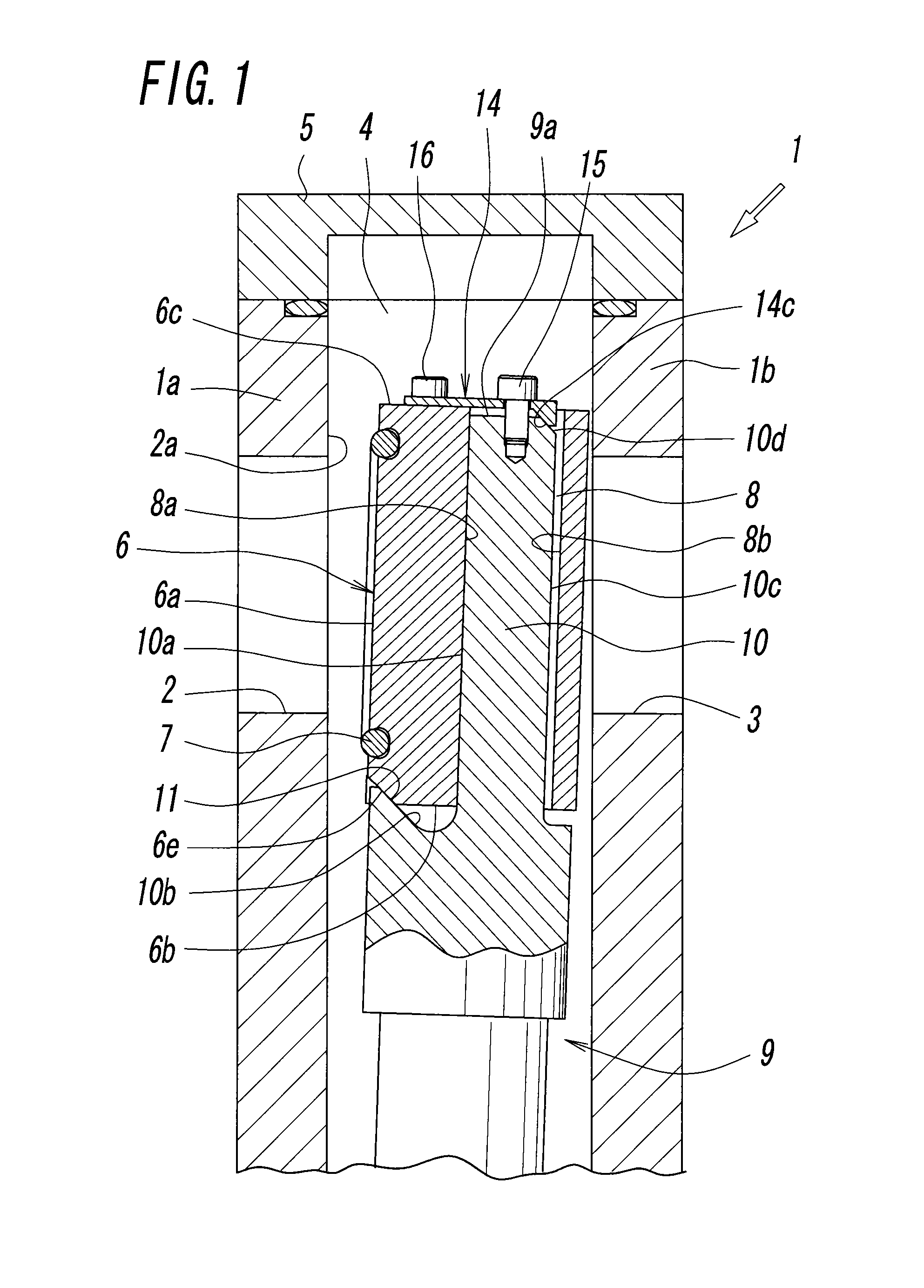
[0011]A technical subject of the present invention is to provide a configuration which satisfies above-described requirements relating to a gate valve that opens and closes the communicating channel of the valve box communicating with the processing chamber with the valve plate and, more specifically, to provide a gate valve which fixes the base side and the tip side of the valve plate mounting portion of the valve rod firmly in a simple mounting structure using a wedge effect or the like, and stabilizes the posture of the valve plate by bringing the joint flat surfaces of the valve plate and the valve rod facing each other strongly into tight contact with each other.
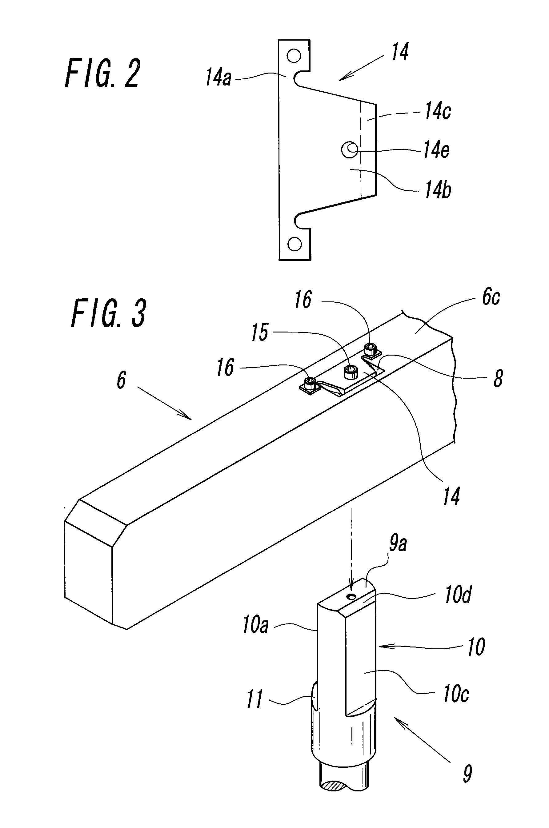
[0013]In the gate valve described above, the valve plate includes a mounting hole which allows insertion of the valve plate mounting portion of the valve rod, and joint flat surfaces which are brought into press-contact with each other when the valve plate and the valve rod are coupled with the coupling plate are formed on the hole surface of the mounting hole and the outer surface of the valve plate mounting portion, respectively. The valve rod includes a depressed-shaped joint shoulder portion which allows fitting of the base side end portion of the valve plate at a position on the side of the base end of the valve plate mounting portion, and the joint shoulder is formed with an inclined surface with which the base side end portion of the valve plate comes into abutment, and the inclined surface causes the valve plate to displace in the direction in which the joint flat surfaces of the valve plate and the valve rod come into press-contact with each other by the wedge effect. The coupling plate couples the valve plate and the valve rod with each other in a state of pressing the valve plate toward the base end side of the valve plate mounting portion.
[0020]Therefore, the valve rod and the valve plate can achieve firm fixation between the joint flat surfaces on the base end side and the tip end side of the valve plate mounting portion of the valve rod with a simple mounting structure using the wedge effect.
[0023]According to the gate valve of the present invention, there is provided a gate valve which fixes the base side and the tip side of the valve plate mounting portion of the valve rod firmly in a simple mounting structure using the wedge effect or the like, and stabilizes the posture of the valve plate by bringing the joint flat surfaces of the valve plate and the valve rod opposing to each other strongly into tight contact with each other.

Problems solved by technology

However, it does not means that high-strength fixing means formed by a highly accurate processing is desired, but means that employment of means which can fix the valve plate firmly in a posture as adequate as possible within a range which allows mounting and demounting operation easily from the opening at the upper end of the valve box, which achieves easy mounting of the valve plate in a stable posture while avoiding the problem of generation of dust or the like, is required.

Method used


Image

  • Gate valve
  • Gate valve
  • Gate valve

Examples


Embodiment Construction

[0030]FIG. 1 to FIG. 3 show Example 1 of a gate valve according to the present invention. This gate valve is configured to be used by being connected to a processing chamber or the like in a semiconductor manufacturing apparatus or the like, includes a communicating hole 2 communicating with the processing chamber or the like on a front wall 1a of a valve box 1, and a seal member (O-ring) 7 disposed in the valve box 1 and configured to come into and out of contact with a valve seat portion 2a around the communicating hole 2 on a seal surface 6a on the front surface of a valve plate 6 which opens and closes the communicating hole 2.

[0031]The valve plate 6 is mounted so as to be mountable and demountable with respect to a valve plate mounting portion 10 formed at the tip end of a valve rod 9, and the valve rod 9 is driven by a drive mechanism, not shown, and displaces the valve plate 6 to positions to open and close the communicating hole 2. More specifically, the valve rod 9 is forme...


PUM


Abstract

In a gate valve including a valve plate connected to a valve plate mounting portion of at a tip end of a valve rod with a connecting plate and configured to open and close a communicating hole of a valve box with the valve plate, the valve plate includes a mounting hole, a joint flat surfaces coming into press-contact with each other, the valve rod includes a depressed-shaped joint shoulder portion, the joint shoulder portion is formed with an inclined surface configured to guide the valve plate in the direction in which the joint flat surfaces are brought into press-contact with each other, and the coupling plate couples the valve plate and the valve rod with each other.

Description

BACKGROUND OF THE INVENTION[0001][1] Field of the Invention[0002]The present invention relates to a gate valve connected to a processing chamber of a semiconductor manufacturing apparatus or the like to open and close a communicating channel communicating with the processing chamber such as a fluid channel or a goods transfer channel.[0003][2] DESCRIPTION OF THE RELATED ART[0004]In Patent Literatures Japanese Unexamined Patent Application Publication No. 2002-195424 and Japanese Unexamined Patent Application Publication No. 2005-291221, a gate valve connected to a processing chamber of a semiconductor manufacturing apparatus or the like and configured to open and close a communicating channel communicating with the processing chamber with a valve plate provided in the interior of the valve box is disclosed. In such a gate valve, since a seal member of the valve plate is subject to damage due to a corrosive fluid such as process gas or the like flowing in the communicating channel, r...

Claims


Application Information

Patent Timeline
Patent Type & Authority Applications(United States)
IPC IPC(8): F16K1/16
CPCF16K51/02F16K3/18F16K3/16F16K3/314
Inventor SHIMODA, HIROMIOGAWA, HIROSHI
Owner SMC CORP
Learn More