Method for the prediction of fatigue life for structures

a technology for structures and life, applied in the direction of structural/machine measurement, instruments, force/torque/work measurement, etc., can solve the problems of fatigue test data loss, structural component overdesign, and current methods that do not predict the variation in fatigue life, so as to reduce fatigue strength

a technology for structures and life, applied in the direction of structural/machine measurement, instruments, force/torque/work measurement, etc., can solve the problems of fatigue test data loss, structural component overdesign, and current methods that do not predict the variation in fatigue life, so as to reduce fatigue strength

US20120271566A1Inactive Publication Date: 2012-10-25DEERE & CO

Image

  • Method for the prediction of fatigue life for structures
  • Method for the prediction of fatigue life for structures
  • Method for the prediction of fatigue life for structures

Examples


Embodiment Construction

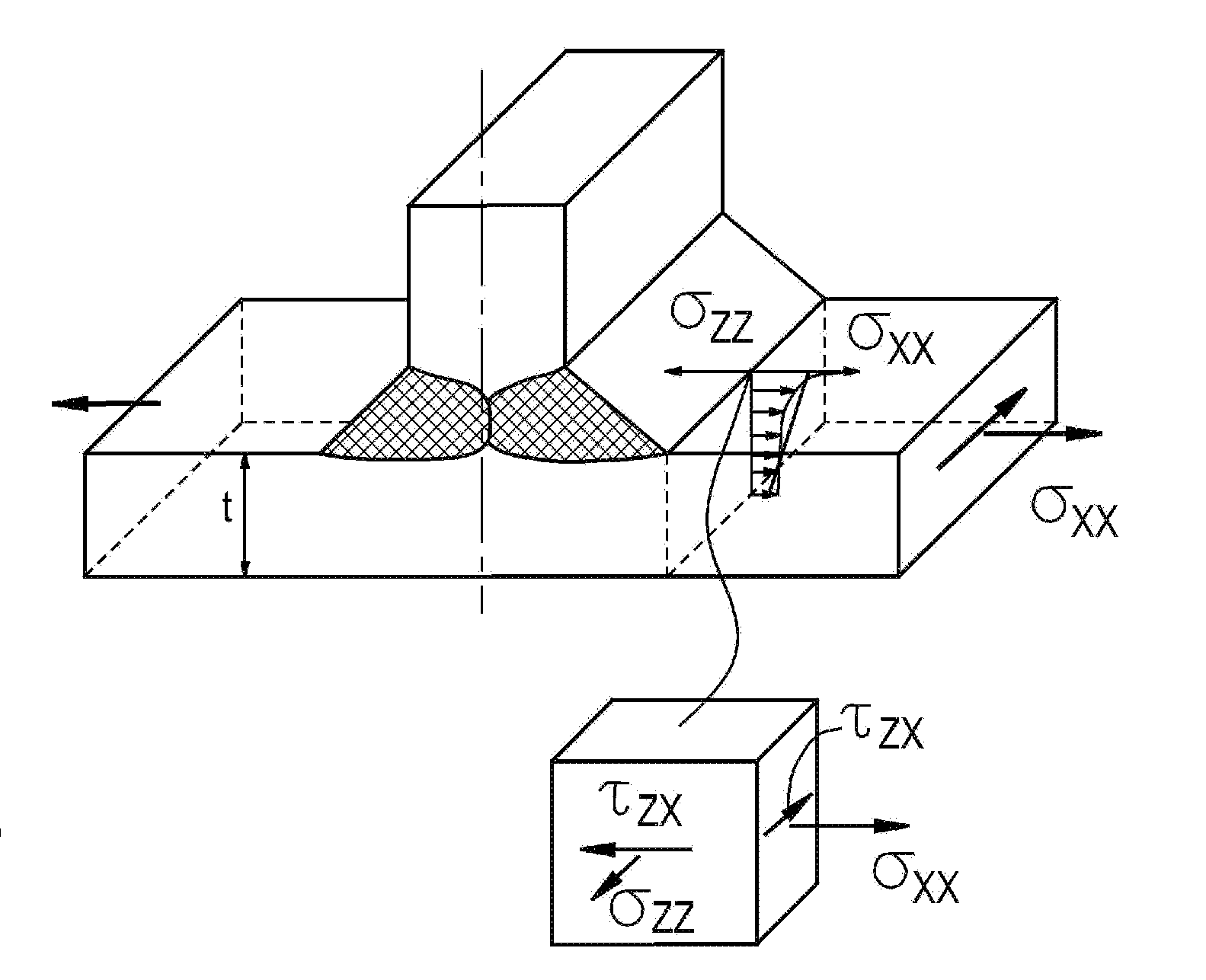
[0036]Referring now to the drawings, the method of the present invention for determining the fatigue life of a structure will be described in greater detail. In the illustrated embodiment, the structure is assumed to be a welded structure, but could be a different type of structure for which it is desirable to determine a fatigue life associated therewith. For example, the structure could be a plate with one or more holes causing localized stress concentrations.

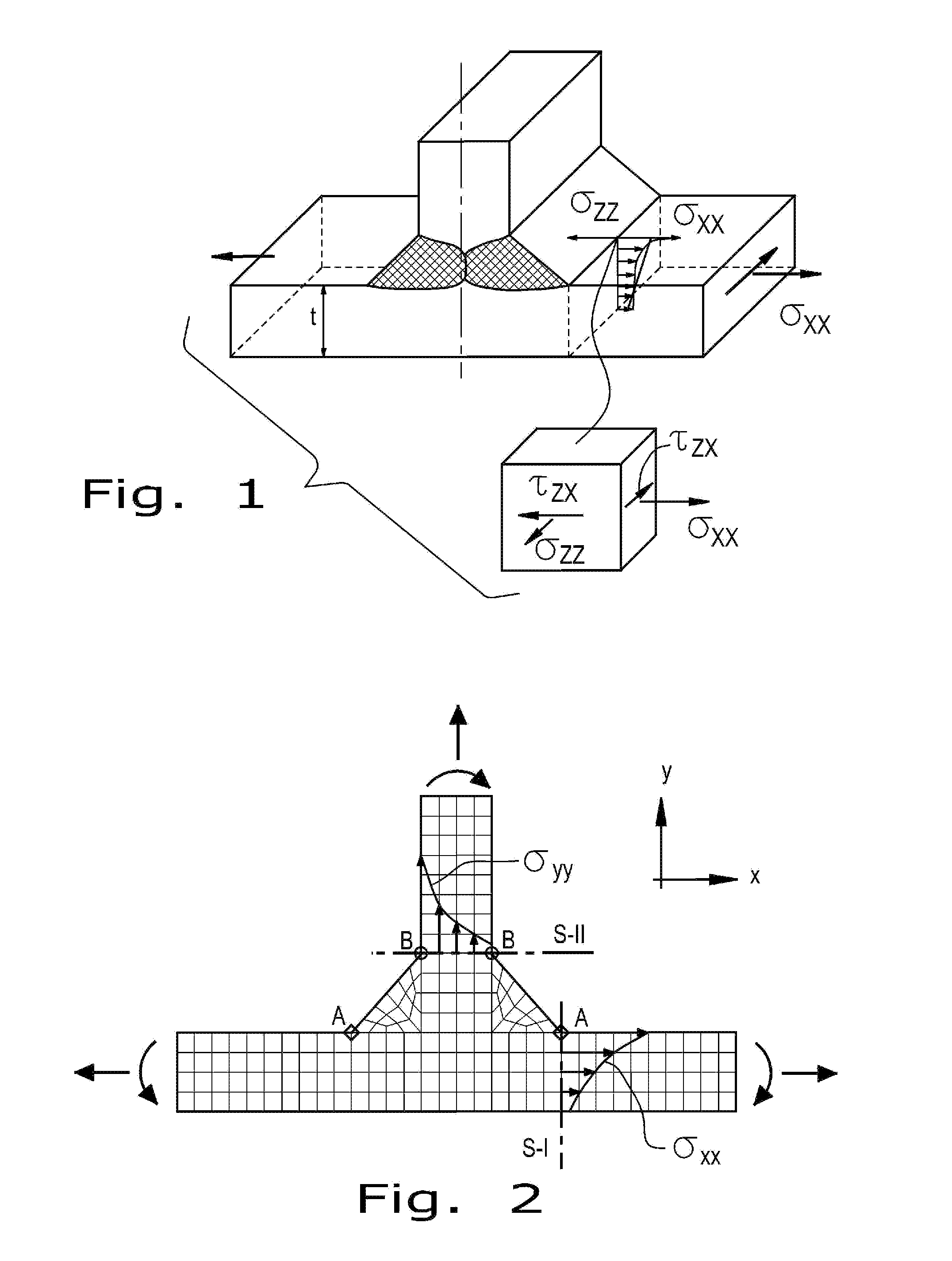
[0037]The welded structure shown in FIG. 1 is assumed to be a 3D geometry of a double fillet T-joint including all geometrical details. Such a structure can be often modeled using either 3D coarse or 3D fine FE mesh. When the coarse FE mesh is used the weld toe is modeled as a sharp corner as shown in FIG. 2. Critical cross sections, i.e., all sections containing the weld toe and the critical points in those sections are denoted by points A and B in both the attachment and the base plate, respectively. The cross section S-I r...


PUM

PropertyMeasurementUnit
fatigue strength coefficientaaaaaaaaaa
fatigue strength exponentaaaaaaaaaa
cyclic modulus of elasticityaaaaaaaaaa

Abstract

A method of determining the fatigue life of a structure includes the steps of:associating a mathematical equation for total strain amplitude with the structure:Δɛ2=σf′E(2Nf)b+ɛf′(2Nf)c,where: Δε / 2=strain amplitude, σf′=fatigue strength coefficient associated with a material of the structure, b=fatigue strength exponent of the material, E=cyclic modulus of elasticity of the material, 2Nf=number of cycles, εf′=fatigue ductility coefficient of the material, and c=fatigue ductility exponent of the material;reducing the fatigue strength exponent (b) such that an elastic portion of a total strain amplitude curve associated with the equation has a reduced slope to account for variable amplitude loading for the structure;generating a total strain amplitude curve, based upon the mathematical equation:Δɛ2=σf′E(2Nf)breduced+ɛf′(2Nf)c,where (breduced) is now the reduced fatigue strength exponent; anddetermining a fatigue life of the structure, based on the total strain amplitude curve with the reduced fatigue strength exponent.

Description

FIELD OF THE INVENTION[0001]The present invention relates to methods for determining the structural integrity of a chassis in work vehicles, and, more particularly, to analysis methods for determining the fatigue life of structures in such work vehicles.BACKGROUND OF THE INVENTION[0002]Work vehicles, such as agricultural, construction, forestry or mining work vehicles, typically include a chassis carrying a body and a prime mover in the form of an internal combustion engine. The chassis may also carry other structural components, such as a front-end loader, a backhoe, a grain harvesting header, a tree harvester such as a feller-buncher, etc.[0003]The chassis itself typically includes a number of structural frame members which are welded together. The size and shape of the frame members varies with the particular type of work vehicle. Given the external loads which are applied to the work vehicle, it is also common to use reinforcing gusset plates and the like at the weld locations o...

Claims


Application Information

Patent Timeline
25 Oct 2012
Publication
US20120271566A1
IPC
G06F19/00
CPC
G06F17/5018; G06F2217/76; G01M5/0033; G01N2203/0212; G01N2203/0073; G06F30/23; G06F2119/04
Inventors
DESHMUKH, VINAYAK; JOHNSON, ERIC M.