Testing system for testing fatigue performance of helicopter main-rotor crossbeam

A test system and fatigue performance technology, which is applied in the field of test system for testing the fatigue performance of the helicopter main propeller girder, can solve the problems of complex loading, fatigue damage, lack of fatigue performance test system, etc., and achieve the effect of high measurement accuracy and convenient operation

Active Publication Date: 2014-09-03
北京堂仁翔科技有限公司
View PDF6 Cites 10 Cited by
  • Summary
  • Abstract
  • Description
  • Claims
  • Application Information

AI Technical Summary

Problems solved by technology

[0002] Engineering structures are subjected to alternating loads during use, and fatigue damage may occur. In order to ensure its safety, it is necessary to test its fatigue performance. After years of technological development, a complete fatigue performance test standard has been formed; however, the helicopter main propeller In the actual working process, the load is complex. The high-speed rotation of the main rotor of the helicopter will generate a large centrifugal force, which will generate a large axial tension at the root of the blade. At the same time, the aerodynamic load of the helicopter will generate alternating bending moments at the root of the blade. , therefore, it is necessary to simulate the complex loading conditions of the main propeller girder of the helicopter, test its fatigue performance, and use it to evaluate the fatigue life; There is no effective fatigue performance test system for the main propeller girder of the helicopter with the axial tension generated by the centrifugal force and the alternating bending moment due to the flapping and shimmy motions.

Method used


Image

  • Testing system for testing fatigue performance of helicopter main-rotor crossbeam
  • Testing system for testing fatigue performance of helicopter main-rotor crossbeam
  • Testing system for testing fatigue performance of helicopter main-rotor crossbeam

Examples


specific Embodiment approach 1

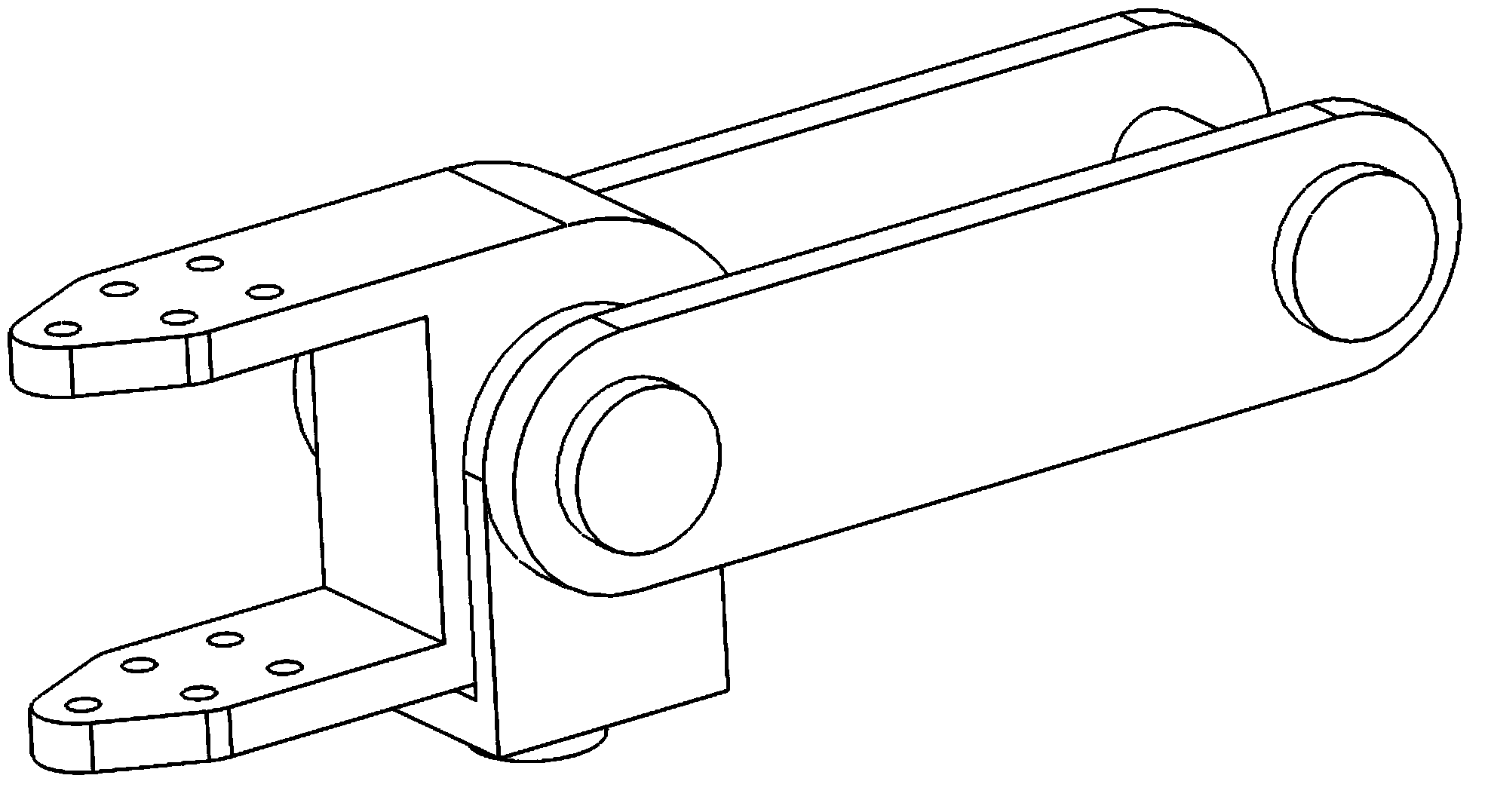
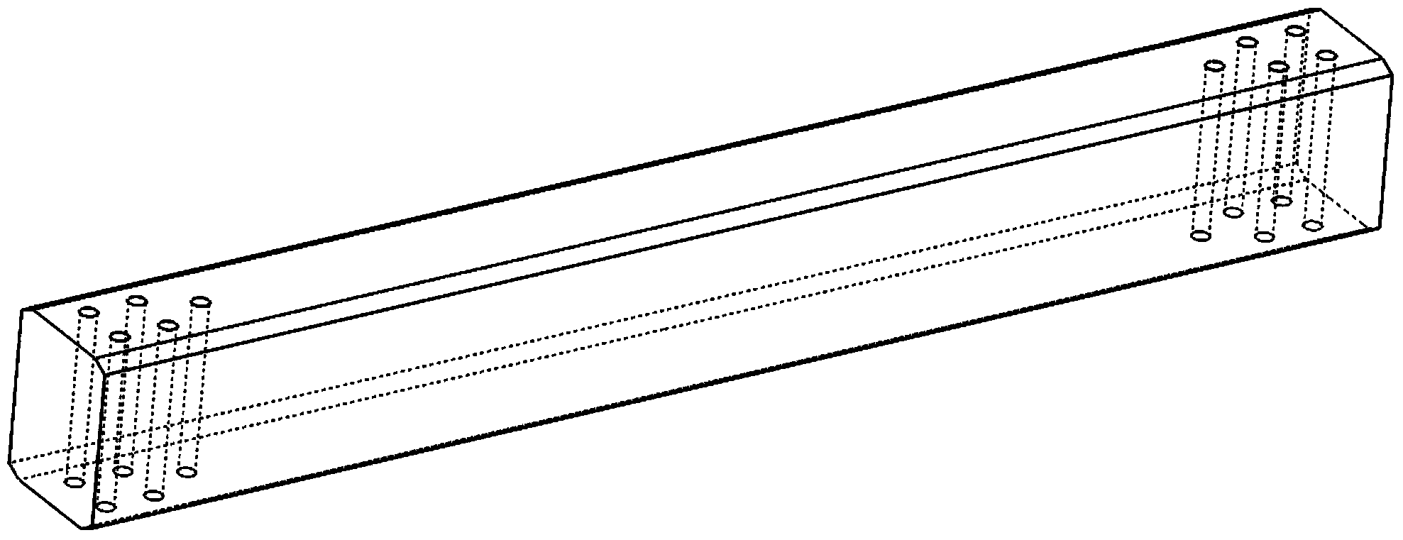
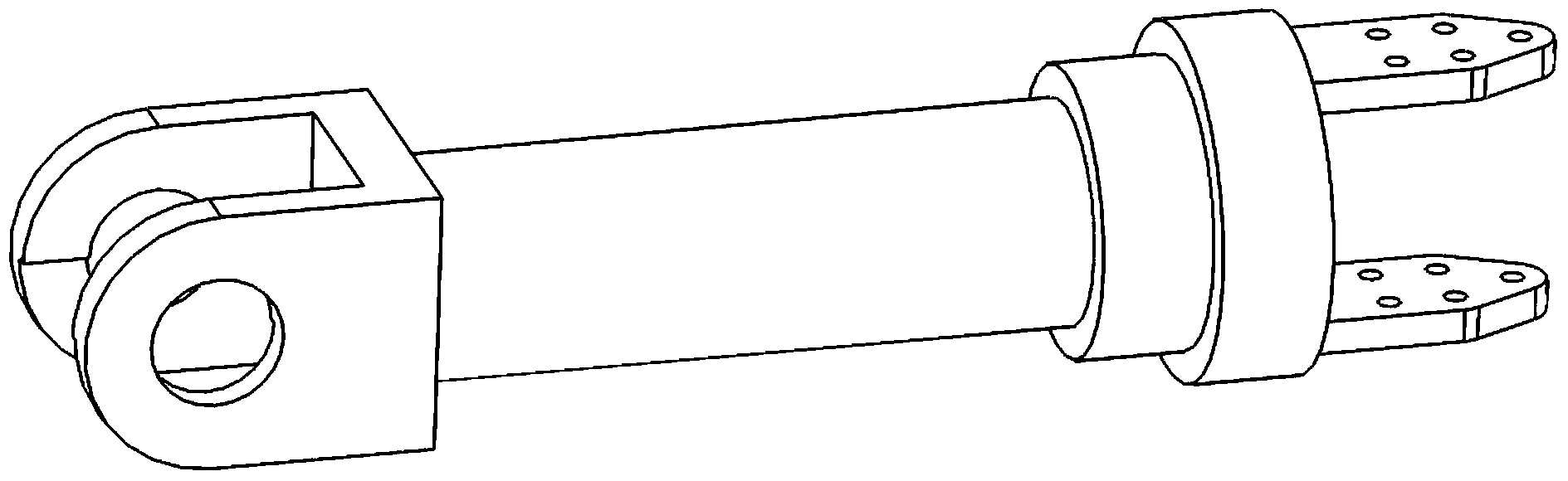
[0028] Specific implementation mode one: combine Figure 7 Specific embodiments of the present invention will be described. The present invention is a test system for testing the fatigue performance of the main propeller girder of a helicopter, which consists of a process joint 1, a strain gauge 2, a test piece 3 at the root of the main propeller girder of a helicopter, a loading joint 4, a hydraulic system 5, a test bench 6, a vibration exciter 7, Composed of motor 8, electric control cabinet, dynamic strain gauge, optical oscilloscope and hydraulic control cabinet. exist Figure 7 Among them, one end of the test piece 3 at the root of the main propeller girder of the helicopter is installed on the process joint 1; 7 is connected with the loading joint 4 and installed on the test bench 6; the motor 8 is connected with the exciter 7; the electric control cabinet is connected with the motor 8; the hydraulic system 5 is connected with the loading joint 4; the hydraulic control...


PUM


Abstract

A testing system for testing fatigue performance of a helicopter main-rotor crossbeam is composed of a helicopter main-rotor crossbeam root test-piece, a process joint, a loading joint, a testing stand, a vibration exciter, a motor, an electric control cabinet, a hydraulic system, a hydraulic control cabinet, strain gages, a dynamic strain meter and a light-beam oscillograph. One end of the helicopter main-rotor crossbeam test-piece is installed on the process joint which is installed on the testing stand. The other end of the helicopter main-rotor crossbeam test-piece is installed on the loading joint. The vibration exciter and the loading joint are connected together and are installed on the testing stand. The motor is connected with the vibration exciter and the electric control cabinet. The hydraulic system is connected with the loading joint and the hydraulic control cabinet. The strain gages are adhered to corresponding positions of the helicopter main-rotor crossbeam test-piece. The dynamic strain meter is connected with the strain gages. The light-beam oscillograph is connected with the dynamic strain meter. The testing system has a simple structure, is convenient to operate and is used for testing fatigue performance of a helicopter main-rotor crossbeam. And a test result has important engineering application value for evaluation of structure fatigue life.

Description

technical field [0001] The invention relates to a test system for testing the fatigue performance of a main propeller girder of a helicopter, and belongs to the technical field of test and test. Background technique [0002] Engineering structures are subjected to alternating loads during use, and fatigue damage may occur. In order to ensure its safety, it is necessary to test its fatigue performance. After years of technological development, a complete fatigue performance test standard has been formed; however, the helicopter main propeller In the actual working process, the load is complex. The high-speed rotation of the main rotor of the helicopter will generate a large centrifugal force, which will generate a large axial tension at the root of the blade. At the same time, the aerodynamic load of the helicopter will generate alternating bending moments at the root of the blade. , therefore, it is necessary to simulate the complex loading conditions of the main propeller g...

Claims


Application Information

Patent Timeline
Patent Type & Authority Applications(China)
IPC IPC(8): G01M13/00
Inventor 熊峻江杨武满孜郁
Owner 北京堂仁翔科技有限公司
Why Eureka
Try Eureka