Heat storage system

a technology of heat storage and energy storage, which is applied in the direction of energy-efficient heating/cooling, space heating and ventilation details, domestic heating details, etc., can solve the problems of insufficient energy level, inability to heat water sufficiently, and inability to draw as much hot water from the storage tank, etc., to enhance the stratification process of the storage tank, the effect of cheap thermal energy and energy-saving

Active Publication Date: 2012-11-01
DANFOSS AS
View PDF22 Cites 14 Cited by
  • Summary
  • Abstract
  • Description
  • Claims
  • Application Information

AI Technical Summary

Benefits of technology

[0012]When using thermal energy it is normal to consider the price and the amount of pollution is involved in the production of the thermal energy. Further it is important that the thermal energy has the required level of energy (eg. that the temperature is high enough). Sometimes it is possible to get thermal energy very cheap (or free), or thermal energy that pollutes very little (or not at all), but the energy level is not high enough. Then the present invention can be very energy efficient by accumulating the energy in one part of the thermal reservoir then making sure that there is usable thermal energy available. As an example, if one has a storage tank that is heated with a solar collector, the solar collector provides free and non-polluting energy, but sometimes during a cloudy day it is not possible to heat the water sufficiently. By using the present invention it is possible to make part of the storage tank sufficiently hot. This is done by cooling another part of the storage tank which can then be heated by the solar collector. Overall this will give the cheapest and least polluting supply of hot water.
[0013]Preferably, the first section and the second section of the thermal reservoir are positioned distant from each other, preferably opposite to each other. When the sections are distant to each other it enhances the stratifying process of storage tank. Between the two, there could be some additional sections that could at least partly be used as barriers between the first and the second sections. An example could be a storage tank with water where energy is transported from the bottom to the top, this stratifies the storage tank.
[0015]Preferably at least one of said additional thermal energy sources is taken from the group, consisting of solar collectors, thermal solar collectors, distributed heating networks, fuel heaters, aerial heat pumps, groundwater heat pumps, geothermal heat pumps, fuel cells and electric heaters. These are all well known thermal energy sources and are fairly affordably and can reliably provide thermal energy. It could be an idea to add more than one thermal energy source of different design, as this will lower the probability of malfunction of the system. Further one could economically optimise the thermal energy production. As an example, if there is both an electric heater and a fuel heater present and the price of electricity and fuel varies from time to time one could minimise the costs of producing thermal energy by using the most cost efficient heater at a specific time.
[0017]Preferably, the thermal reservoir comprises a fluid, preferably a watery fluid. Storing thermal energy in a fluid is an advantage, because it is easy to both draw and feed the energy to and from a fluid and thus the thermal reservoir. Fluid that as a majority consists of water has the advantage that water has some very good thermodynamic properties for storing thermal energy. The specific heat capacity is very high and it is available almost everywhere and is relatively harmless in the case of a leak in the system.
[0019]Preferably the first part and / or the second part are further, at least at times able to supply fluid to the fluid thermal reservoir having a different temperature level than the average temperature level in the thermal reservoir, preferably a higher and / or lower temperature level than the average temperature level in the thermal reservoir. By constructing the thermal storage system this way one can minimize the work that needs to be done by the active thermal energy transfer means to get a section of the thermal reservoir that has a sufficiently high temperature.
[0022]Preferably, at least in part and / or at least at times, a thermal energy transfer is performed by fluid flow between at least one third section of the thermal reservoir and at least one of the first sections of the thermal reservoir and / or at least one of the second sections of the thermal reservoir. Drawing fluid from a third section and using the active thermal energy transfer means to heat and cool the fluid and at least in part return the fluid to either the first section and / or the second section causes that the active thermal energy transfer means can be operated in an efficient mode where the work done by the active thermal energy transfer means can be minimised in relation to the transfer of the thermal energy.

Problems solved by technology

Of course it is not possible to draw as much hot water from the storage tank as from the system where you simply heat the system, but that is because, contrary to prior art, thermal energy is not added to the system in any significant amount.
Sometimes it is possible to get thermal energy very cheap (or free), or thermal energy that pollutes very little (or not at all), but the energy level is not high enough.
As an example, if one has a storage tank that is heated with a solar collector, the solar collector provides free and non-polluting energy, but sometimes during a cloudy day it is not possible to heat the water sufficiently.

Method used


Image

  • Heat storage system
  • Heat storage system
  • Heat storage system

Examples


Embodiment Construction

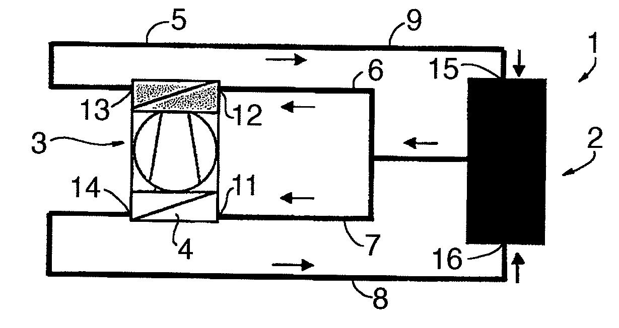
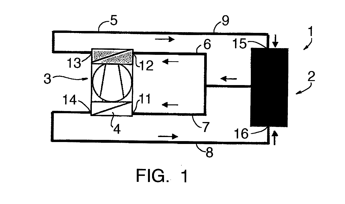
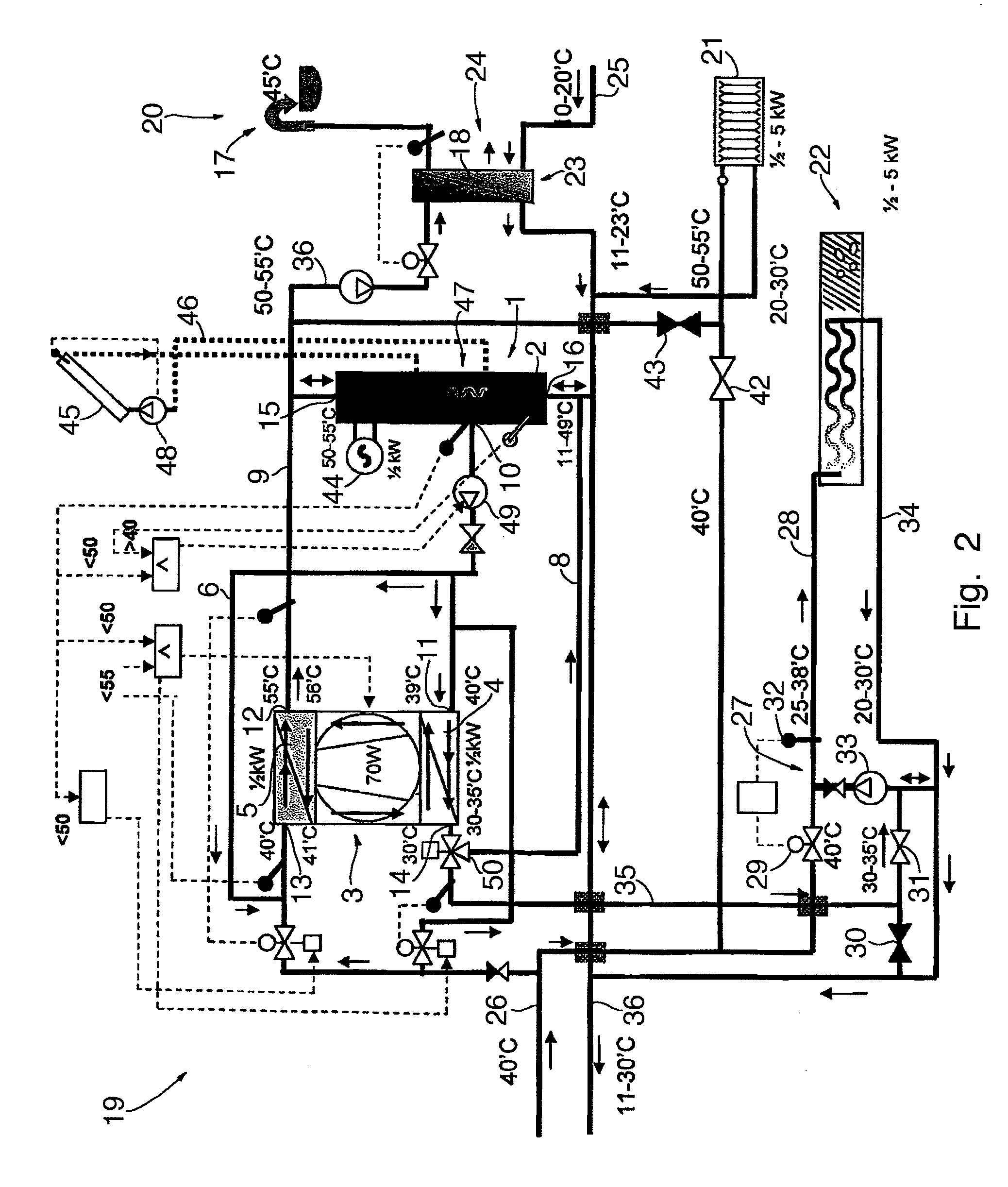
[0028]To simplify the further discussion, all figures show temperature values. The values given are only examples of possible temperatures and / or temperature ranges, and are not intended to limit the invention in any way.

[0029]FIG. 1 shows a first possible embodiment of a heat storage system 1. The heat pump 3 is shown in schematic view, hence only a schematic of the circuit, the low-temperature part 4 and the high-temperature part 5 are shown. For a more detailed description of a heat pump 3, see FIG. 3, and description below. In short the heat pump 3 is able to transport heat from the low-temperature part 4 to the high-temperature part 5. FIG. 1 also shows a storage tank 2. The storage tank 2 is filled with a fluid. The fluid could be water or water with additives where the additives could have the properties of inhibiting bacterial growth in the water and / or the corrosive effect of water on the system and / or in other way preventing the water to change its physical and chemical pr...


PUM


Abstract

The invention relates to a thermal energy storage system comprising at least one thermal reservoir and at least one thermal energy transfer means that, at least at times, are able to transfer thermal energy from at least one first section of the thermal reservoir to at least one second section of the thermal reservoir. The invention also relates to a method changing the energy distribution of a thermal reservoir wherein thermal energy is transferred from at least one first section of the thermal reservoir to at least one second section of the thermal reservoir.

Description

CROSS REFERENCE TO RELATED APPLICATIONS[0001]This application is entitled to the benefit of and incorporates by reference essential subject matter disclosed in International Patent Application No. PCT / DK2010 / 000119 filed on Aug. 24, 2010 and Danish Patent Application No. PA 2009 00957 filed Aug. 25, 2009.FIELD OF THE INVENTION[0002]The invention relates to a thermal energy storage system comprising at least one thermal reservoir and at least one thermal energy transfer means that at least at times are able to transfer thermal energy from at least one first section of the thermal reservoir to at least one second section of the thermal reservoir.BACKGROUND OF THE INVENTION[0003]A thermal energy storage system can be used to store thermal energy in a thermal reservoir. Storing thermal energy in a thermal reservoir is well known. There are a multitude of reasons for storing energy in a thermal reservoir, among them: If it is desired to be able to reliably draw thermal energy of a level ...

Claims


Application Information

Patent Timeline
Patent Type & Authority Applications(United States)
IPC IPC(8): F28D15/00F24J2/04
CPCF24D11/0221F24D11/0228F24D17/02Y02B30/126Y02B10/20Y02B10/40Y02B10/70F24D19/1078Y02B30/12
Inventor KRISTJANSSON, HALLDOR
Owner DANFOSS AS
Why Eureka
Try Eureka