Apparatus or circuit for driving a DC powered lighting equipment

Active Publication Date: 2012-11-01
CITY UNIVERSITY OF HONG KONG +1
View PDF34 Cites 18 Cited by
  • Summary
  • Abstract
  • Description
  • Claims
  • Application Information

AI Technical Summary

Benefits of technology

[0009]An object of the invention is to mitigate or obviate to some degree

Problems solved by technology

However, as they cannot be directly connected to the ac mains, they are driven by a device called a ballast.
This is a serious concern for landfills and waste incinerators where the mercury may be released and contribute to air and water pollution.
However, where this has been tried before, although the existing fluorescent lamp fixtures may remain uncha

Method used


Image

  • Apparatus or circuit for driving a DC powered lighting equipment
  • Apparatus or circuit for driving a DC powered lighting equipment
  • Apparatus or circuit for driving a DC powered lighting equipment

Examples


Embodiment Construction

[0044]The following description is of a preferred embodiment by way of example only and without limitation to the combination of features necessary for carrying the invention into effect.

[0045]The invention relates to an apparatus or circuit that can operate with electronic ballasts for electric discharge lamps to drive dc-powered lighting equipment and more particularly to an apparatus or circuit for modifying existing circuits for driving dc powered lighting equipment to accept light emitting diode ‘LED’ lamps without requiring the replacement of any electronic ballast circuitry for the existing dc powered lighting equipment circuitry. References herein to “lighting equipment”, light element“, “lamp” and “lamp element” will be taken to refer to the same technical feature, namely a light element as exemplified by a de-powered, solid-state light element such as an LED.

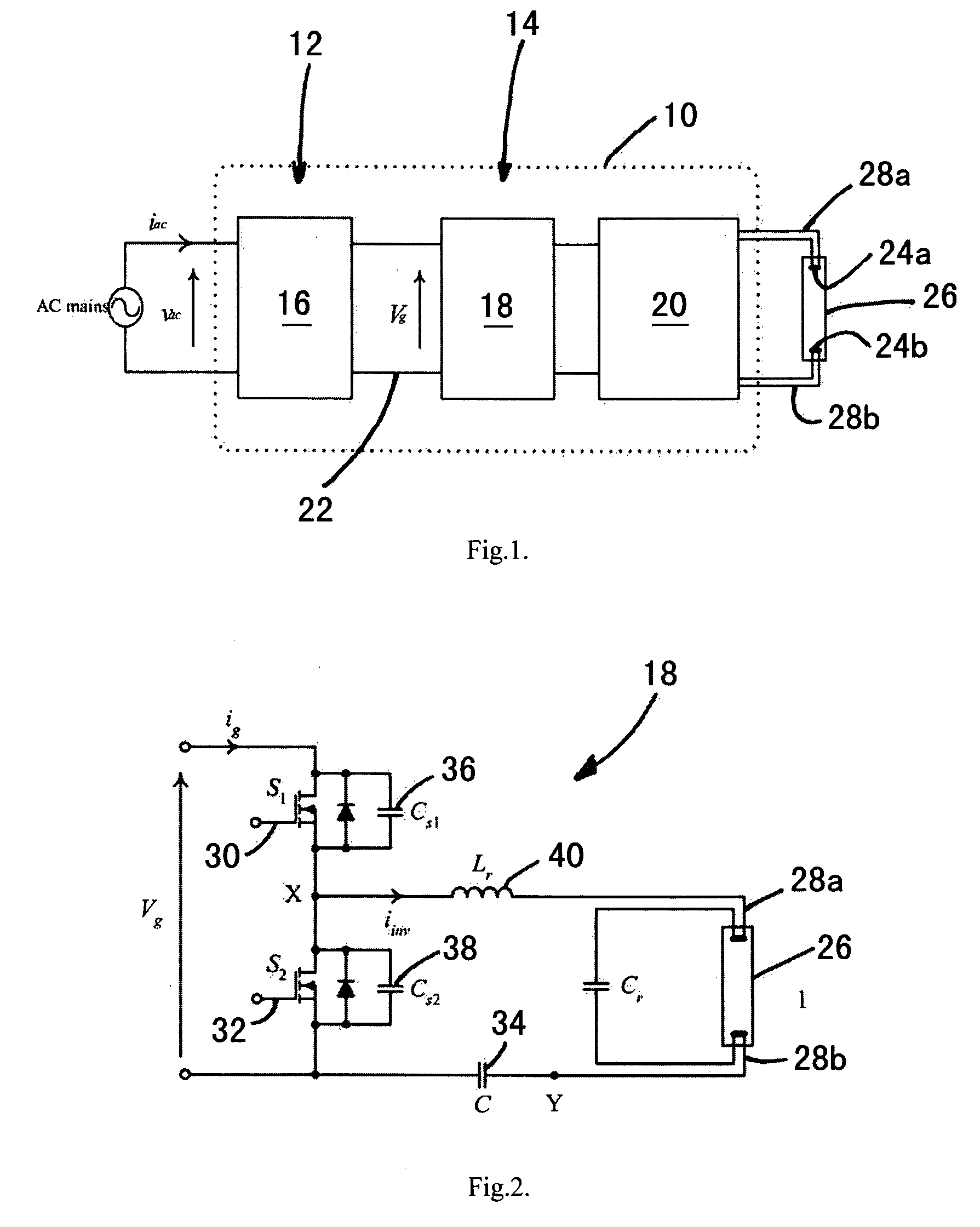
[0046]By way of understanding the context of the invention, a basic block schematic diagram of a conventional modern...


PUM


Abstract

An apparatus that can operate with electronic ballasts (10) for electric discharge lamps to drive dc-powered lighting equipment (26) is provided. The apparatus is directly connected to the output of the electronic ballast (10) and is then used to control the power being supplied to the dc-powered lighting equipment (26). The maximum power delivered to the dc-powered lighting equipment (26) is substantially equal to the rated output power of the electronic ballast (10). A switching converter is acted as the necessary input impedance for the electronic ballast (10). Thus, the active power and reactive power drawn from the electronic ballast (10) can be controlled. The output of the switching converter provides dc power for the dc-powered lighting equipment (26).

Description

FIELD OF THE INVENTION [0001]The invention relates to an apparatus or circuit that can operate with electronic ballasts for electric discharge lamps to drive dc-powered lighting equipment and more particularly to an apparatus or circuit for modifying existing circuits for powering lighting equipment to accept light emitting diode ‘LED’ lamps without requiring the replacement of any electronic ballast circuitry for the existing lighting equipment circuitry.BACKGROUND OF THE INVENTION[0002]Gas discharge lamps have been widely used in various residential, commercial and industrial sectors because of their high efficacy (lumen per watt). However, as they cannot be directly connected to the ac mains, they are driven by a device called a ballast. The ballast generates a high voltage and applies it across the two ends of the lamp to ignite it. The ballast also regulates the current flowing through the lamp.[0003]Ballasts can be categorized into two main types, namely electromagnetic and el...

Claims


Application Information

Patent Timeline
IPC IPC(8): H05B37/02H05B44/00
CPCF21V23/02F21Y2101/02Y02B20/346H05B33/0815H05B33/0809F21Y2115/10H05B45/39Y02B20/30H05B45/3725
Inventor CHUNG, HENRY SHU HUNGCHEN, NAN
Owner CITY UNIVERSITY OF HONG KONG
Why Eureka
Try Eureka