Vehicle compartment door handle assembly

a technology for vehicle compartments and handle assemblies, applied in the direction of electrical locking circuits, transportation and packaging, lock applications, etc., can solve the problems of handle assemblies having limited options, other electronic or electromechanical features, corrosion, etc., and achieve the effect of preventing unauthorized manipulation of the lock arm

Active Publication Date: 2012-11-01
TRI MARK CORP
View PDF59 Cites 18 Cited by
  • Summary
  • Abstract
  • Description
  • Claims
  • Application Information

AI Technical Summary

Benefits of technology

[0019]A lock assembly includes a housing with snap fit geometry to accept a lock cylinder escutcheon. The lock assembly includes a pivotal lock arm connected to the lock cylinder, with a security or anti-theft plate residing between the lock arm and the housing to preclude unauthorized manipulation of the lock arm. The latch rotor has a leg which engages an optional position switch in the mounting bracket to sense the position of the rotor. An optional reversible motor and actuator may be provided in the mounting bracket to control pivotal movement of the lock arm between locked and unlocked positions via a remote key fob or other access user interface. The mount bracket may also include one or more LEDs that flash in pre-determined method through lens of the housing to indicate a locked condition of the lock assembly and an unlocked condition of the lock assembly. The mounting bracket may be selected from first and second interchangeable brackets, with the first bracket including optional electronic features, such as LED indicators, door ajar rotor position switch, and the motor and actuator for remote power actuation of the lock assembly and the second bracket being adapted for manual actuation of the lock assembly.

Problems solved by technology

Some handle assemblies have limited options, such as power locking, but not other electronic or electromechanical features.
Different problems exist for these prior art handles, such as corrosion, cycle life, finger clearance, security, handed requirements, assembly, installation, and interchangeability.
Also, some handle assemblies are designed for high volume applications, but are not practical for low to medium volume applications, such as service truck bodies, RV motor homes, construction equipment, agricultural equipment and other trucks.

Method used


Image

  • Vehicle compartment door handle assembly
  • Vehicle compartment door handle assembly
  • Vehicle compartment door handle assembly

Examples


Embodiment Construction

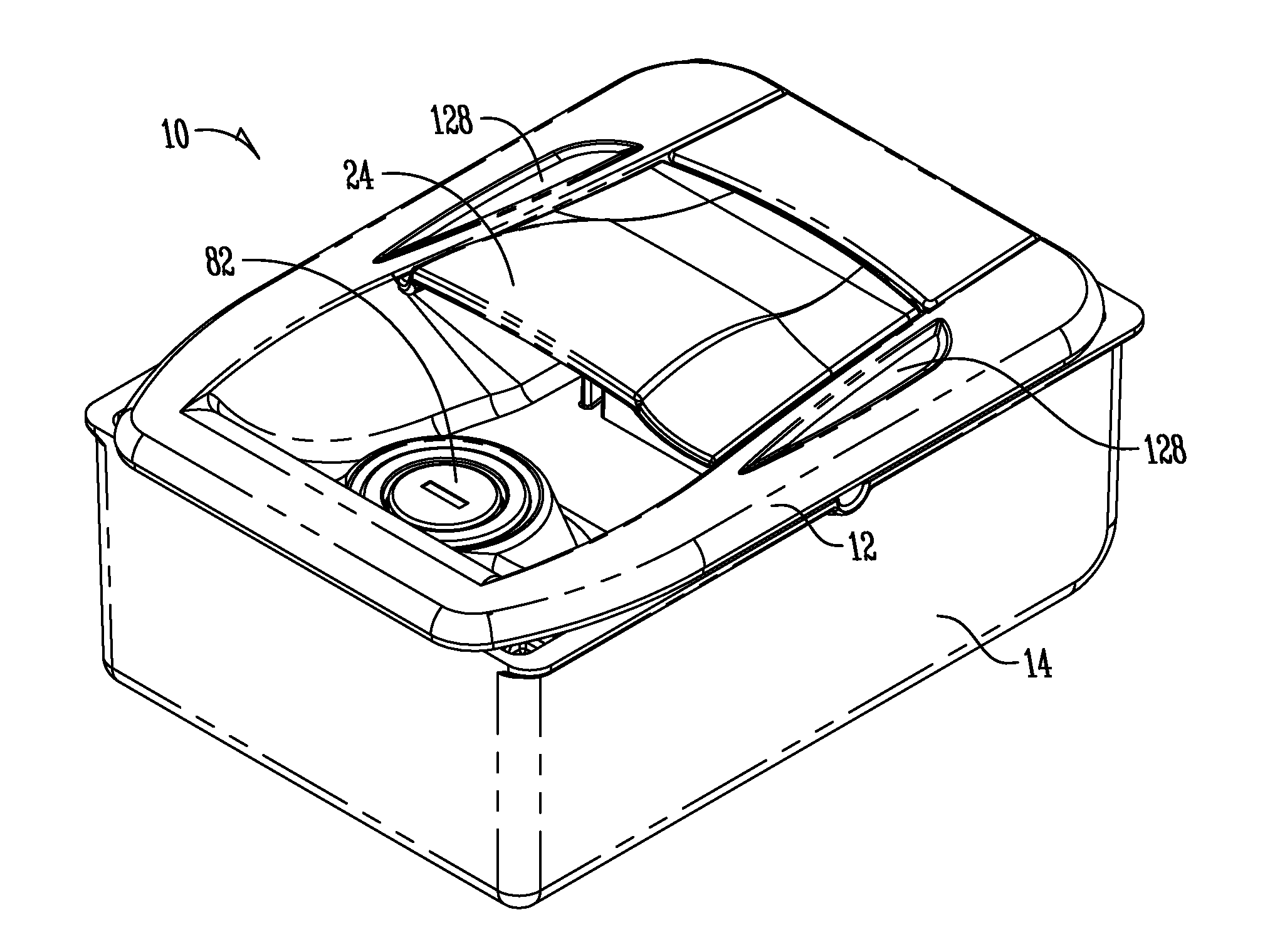
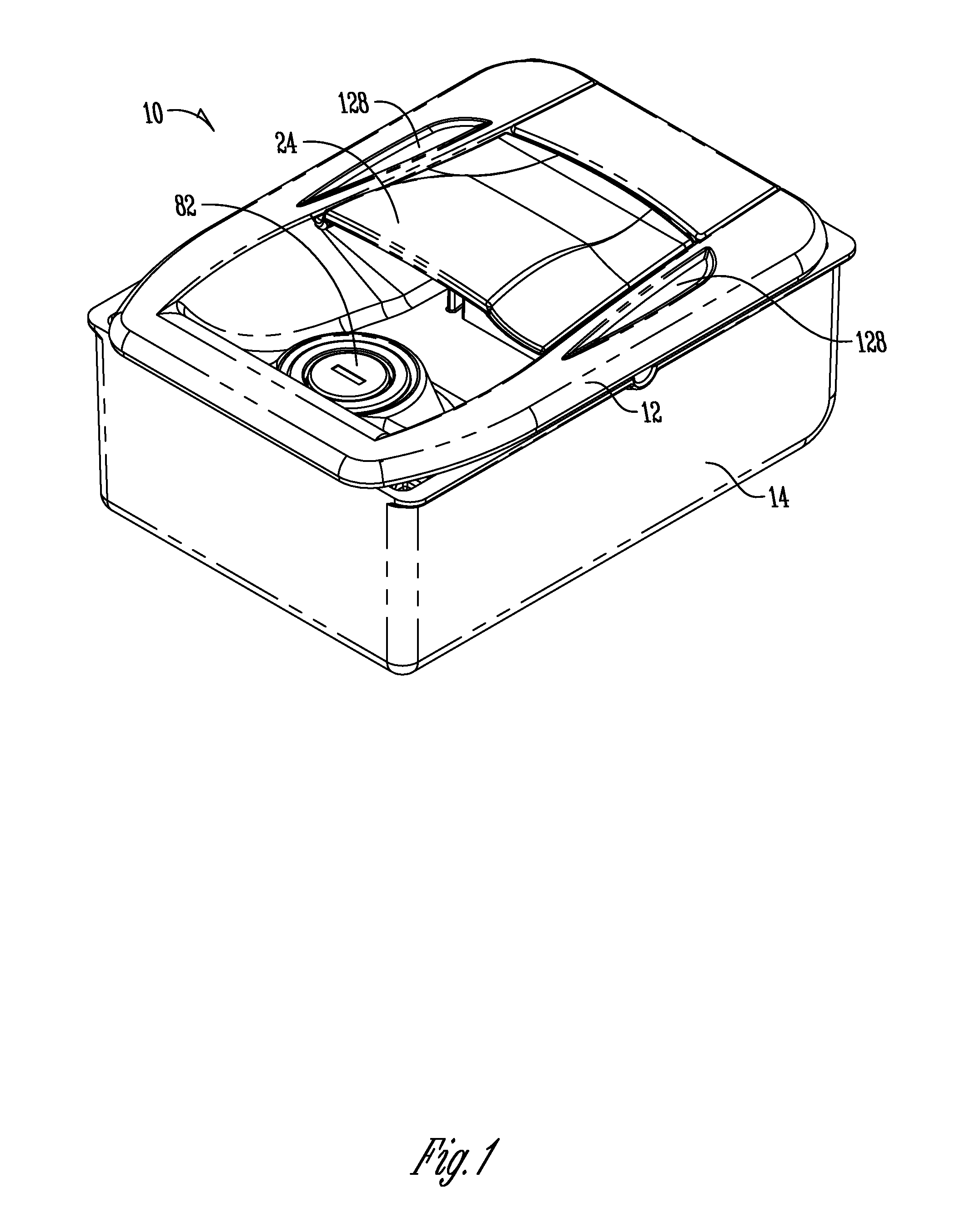
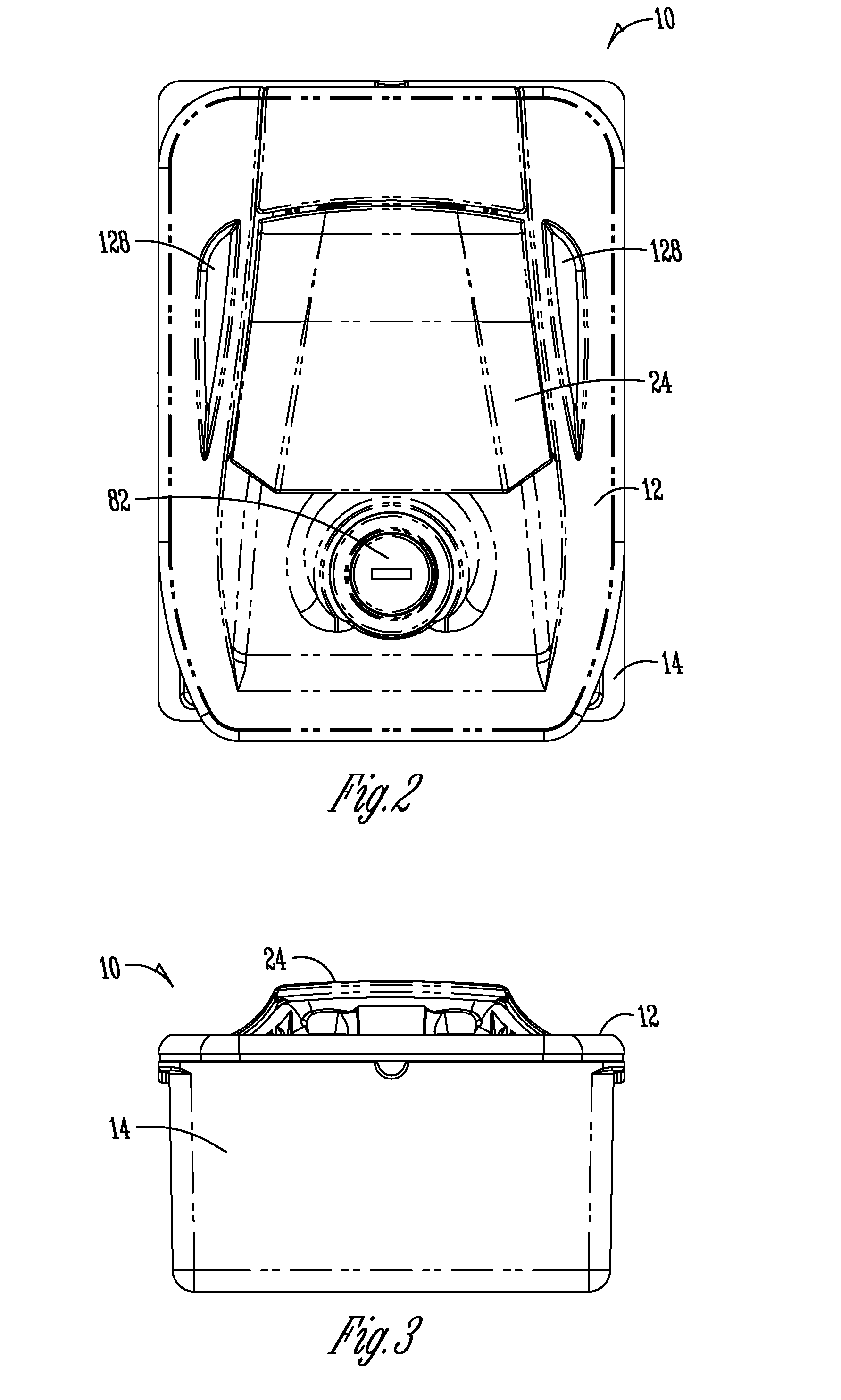
[0048]The handle assembly of the present invention is generally designated by the reference numeral 10 in the drawings. This handle assembly 10 is intended for use on compartment doors on various types of vehicles, such as service truck bodies, RV motor homes, agricultural equipment, construction equipment, and other trucks. The handle assembly 10 is mounted in the compartment door in any convenient manner. The handle assembly 10 generally includes a front or outer housing 12 and a rear mounting box or bracket 14. The front housing 12 has a plurality of rearwardly extending legs 16 which align with bosses 18. Screws (not shown) extend forwardly through counter bore holes 19 in the back wall 20 of the mounting bracket 14 for receipt in the legs 16, thereby securing the front or outer housing 12 to the mounting box or bracket 14[rlm1]. A sealing gasket 13 is provided between the housing 12 and the outer skin of the door to keep our moisture, dust and other contaminants.

[0049]The housi...


PUM


Abstract

A handle assembly is provided for a door of a vehicle storage or baggage compartment and includes a latch module press fit onto the housing of the assembly. The handle assembly also includes a lock assembly with a security plate to preclude unauthorized manipulation of the lock arm. In one embodiment, a position switch is associated with the latch rotor to sense the unlatched position of the rotor. A remote control power unit may also be provided on the handle assembly for locking and unlocking the latch module via a key fob or other access system user interface. An LED may be associated with the power unit to indicate locking and unlocking events, or other vehicle status information. The mounting bracket of the assembly may be selected from interchangeable brackets for manual or power actuation of the lock assembly.

Description

BACKGROUND OF THE INVENTION[0001]Handle assemblies for vehicle compartment doors come in a variety of configurations and are mounted to the door in numerous manners. Some handle assemblies have limited options, such as power locking, but not other electronic or electromechanical features. Different problems exist for these prior art handles, such as corrosion, cycle life, finger clearance, security, handed requirements, assembly, installation, and interchangeability. Also, some handle assemblies are designed for high volume applications, but are not practical for low to medium volume applications, such as service truck bodies, RV motor homes, construction equipment, agricultural equipment and other trucks.[0002]Accordingly, a primary objective of the present invention is the provision of an improved vehicle compartment door handle assembly which overcomes the problems associated with the prior art handle assemblies.[0003]Another objective of the present invention is the provision of...

Claims


Application Information

Patent Timeline
Patent Type & Authority Applications(United States)
IPC IPC(8): B60Q1/00E05B65/12B60Q1/26E05B3/00
CPCE05B85/18E05B41/00E05B77/44E05B79/04E05B85/06E05B81/16E05B81/36E05B81/66E05B83/16E05B81/06E05B5/00Y10T70/5155Y10T292/57
Inventor BURNS, JAYDEN F.BEARMAN, JENNIFER L.ROOT, DAVID L.MAGNER, DAVID S.WILDEBOER, CHRIS J.NJUS, TIMOTHY J.
Owner TRI MARK CORP
Why Eureka
Try Eureka