Pseudo-Sunlight Irradiating Apparatus

a technology of irradiating apparatus and sunlight, which is applied in the direction of lighting and heating apparatus, fixed installation, instruments, etc., can solve the problems of variable inconveniences and extremely difficult irradiation, and achieve uniform illuminance distribution, suppress the uneven illuminance of light, and adjust the light transmittance

Inactive Publication Date: 2012-11-01
SHARP KK
View PDF4 Cites 5 Cited by
  • Summary
  • Abstract
  • Description
  • Claims
  • Application Information

AI Technical Summary

Benefits of technology

[0020]According to a pseudo-sunlight irradiating apparatus of the present invention, it is possible to adjust a transmittance of light by employing a transmittance adjusting member that has a wavelength dependency which varies in accordance with wavelength of the light whose transmittance needs to be adjusted. Therefore, even if a region where a transmittance of light needs to be adjusted and a region where a transmittance of the other light needs to be adjusted coexist on an irradiation surface, the transmittance of the light and the transmittance of the other light can be adjusted simultaneously. It is thus possible to uniform illuminance distribution by adjusting the transmittance, provided that the transmittance adjusting member having the wavelength dependency which varies in accordance with the wavelength of the light whose transmittance needs to be adjusted is provided in a region where illuminance unevenness occurs, that is, a region where the transmittance needs to be adjusted. In other words, it is possible to suppress the illuminance unevenness of the light that is emitted toward the irradiation surface.

Problems solved by technology

Otherwise, users predict that various inconveniences will occur when they use the solar cell.
However, the pseudo-sunlight irradiating apparatus has a problem that it is extremely difficult to irradiate, with light whose illuminance is uniform, a whole planar light receiving surface (or a whole region) of a solar cell.

Method used


Image

  • Pseudo-Sunlight Irradiating Apparatus
  • Pseudo-Sunlight Irradiating Apparatus
  • Pseudo-Sunlight Irradiating Apparatus

Examples


first embodiment

[0057](Configuration of Pseudo-Sunlight Irradiating Apparatus 18)

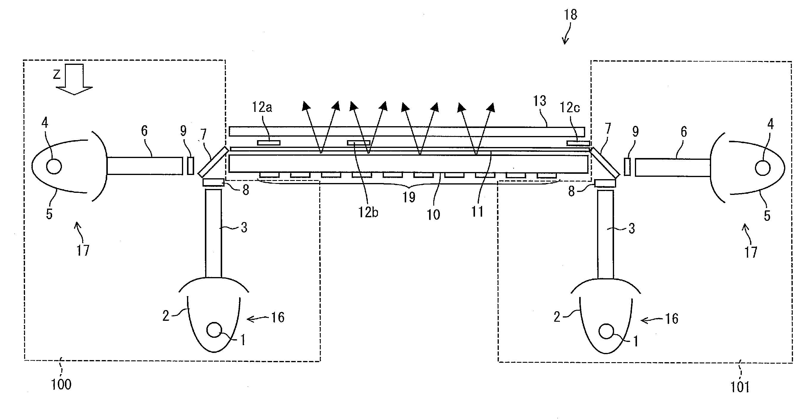
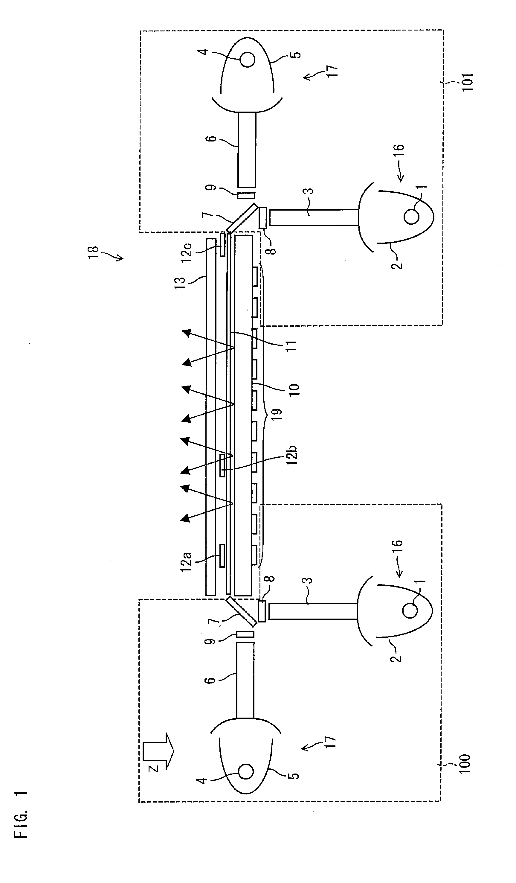
[0058]The following description discusses an embodiment of the present invention with reference to drawings. First, the following description discusses, in detail with reference to FIG. 1, a pseudo-sunlight irradiating apparatus 18 that irradiates an irradiation surface 13 with pseudo sunlight. FIG. 1 shows a major configuration of the pseudo-sunlight irradiating apparatus 18. The pseudo sunlight is a type of artificial light, and has an emission spectrum extremely similar to that of natural light (sunlight). The pseudo-sunlight irradiating apparatus 18 of the present embodiment irradiates the irradiation surface 13 with composite light of xenon light and halogen light as pseudo sunlight. For example, a solar cell is provided in a place where the irradiation surface 13 is located.

[0059]As shown in FIG. 1, the pseudo-sunlight irradiating apparatus 18 includes optical system sets 100 and 101, a light guide plate 10 and a...

second embodiment

[0100](Configuration of Pseudo-Sunlight Irradiating Apparatus38)

[0101]The following describes another embodiment of the present invention with reference to drawings. In a pseudo-sunlight irradiating apparatus of the present embodiment, illuminance adjusting members are made up of two types of transmittance adjusting sheets. FIG. 6 shows a main configuration of a pseudo-sunlight irradiating apparatus 38 of the present embodiment. As shown in FIG. 6, the pseudo-sunlight irradiating apparatus 38 includes optical system sets 100 and 101 each including a xenon light source 16 and a halogen light source 17, a light guide plate 10 and a prism sheet 11. A transmittance adjusting sheet (transmittance adjusting member) 31 and a transmittance adjusting sheet (transmittance adjusting member) 32a provided on the transmittance adjusting sheet 31 are provided, between the prism sheet 11 and an irradiation surface 13, so that the transmittance adjusting sheet (transmittance adjusting member) 32a is...

third embodiment

[0116](Configuration of Pseudo-Sunlight Irradiating Apparatus 48)

[0117]The following describes a further embodiment of the present invention with reference to drawings. It is preferable that the number of the transmittance adjusting sheets on the prism sheet 11 is smaller. This is because, as the number becomes smaller, (i) the number of the constituents of the pseudo-sunlight irradiating apparatuses 18 or 38 becomes smaller and (ii) the distance between the irradiation surface 13 and the transmittance adjusting sheet becomes shorter. Therefore, a pseudo-sunlight irradiating apparatus of the present embodiment has just a single transmittance adjusting sheet. FIG. 14 shows a main configuration of a pseudo-sunlight irradiating apparatus 48 of the present embodiment. As shown in FIG. 14, the pseudo-sunlight irradiating apparatus 48 includes optical system sets 100 and 101 each including a xenon light source 16 and a halogen light source 17, a light guide plate 10 and a prism sheet 11. ...


PUM


Abstract

A pseudo-sunlight irradiating apparatus (18) includes optical system sets (100 and 101) each including a xenon light source (16) and a halogen light source (17), a light guide plate (10) and a prism sheet (11). Transmittance adjusting sheets (12a to 12c) are provided on the prism sheet (11). The transmittance adjusting sheets (12a to 12c) have at least one of properties in which (i) most light whose wavelength is shorter than a predetermined wavelength pass through and most light whose wavelength is longer than the predetermined wavelength is reflected and (ii) most light whose wavelength is shorter than the predetermined wavelength is reflected and most light whose wavelength is longer than the predetermined wavelength pass through. It is thus possible to independently adjust a transmittance of xenon light and a transmittance of halogen light.

Description

TECHNICAL FIELD[0001]The present invention relates to a pseudo-sunlight irradiating apparatus that irradiates an irradiation surface with pseudo sunlight.BACKGROUND ART[0002]The importance of a solar cell has been recognized as a clean energy source, and demand for the solar cell has increased. The solar cell is used in various technical fields ranging from power sources for large-sized electric equipments to small power sources for precision electronic devices. If the solar cell is to be widely used in various technical fields, then properties of the solar cell, particularly, an output property of the solar cell should be precisely measured. Otherwise, users predict that various inconveniences will occur when they use the solar cell. Therefore, especially a technique is demanded which is available to inspection, measurement and testing of the solar cell and which can irradiate a large area with high-accuracy pseudo sunlight.[0003]To comply with the demand, a pseudo-sunlight irradia...

Claims


Application Information

Patent Timeline
Patent Type & Authority Applications(United States)
IPC IPC(8): F21V9/02F21Y101/00
CPCF21S8/006G02B6/0026G02B6/007G02B6/005G02B6/0068G02B6/0028
Inventor MINAMI, KOHJINAKAMURA, ATSUSHI
Owner SHARP KK
Why Eureka
Try Eureka