Raise-Assist and Smart Energy System for a Pipe Handling Apparatus

a technology of lifting assistance and smart energy system, which is applied in the field of pipe handling apparatus, can solve the problems of increasing or decreasing pushing and braking forces, and achieve the effects of increasing or decreasing the stiffness increasing or decreasing the pushing and braking force, and reducing the force of the pneumatic spring

Inactive Publication Date: 2012-11-01
SCHLUMBERGER TECH CORP
View PDF10 Cites 2 Cited by
  • Summary
  • Abstract
  • Description
  • Claims
  • Application Information

AI Technical Summary

Benefits of technology

[0029]The pneumatic spring assembly comprises a cylinder having one end pivotally coupled to the boom and a piston slidably received in the cylinder and extending outwardly therefrom. The piston is pivotally coupled to the frame. The piston defines a gas-containing space within the cylinder. This gas-containing space is filled with a compressible fluid. In the preferred embodiment of the present invention, the compressible fluid is a nitrogen gas. A gas-charging assembly is fluidically coupled to the gas-containing space so as to pass the compressible fluid into the gas-containing space. The gas-charging assembly may be connected to a reservoir for containing compressible fluid. The reservoir may be used to increase or decrease the amount of compressible gas within the cylinder of the pneumatic spring, which in turn increases or decreases the stiffness of the pneumatic spring. This results in increased or decreased pushing and braking forces that the pneumatic spring may exert on the boom.
[0030]In a preferred embodiment of the present invention, the gas-charging assembly may further comprise a feedback mechanism for monitoring the pressure in the gas-containing space, as well as the current load upon the boom as the boom travels between the first and second positions. The feedback mechanism may also operate in real-time for actively monitoring the pressure in the gas-containing space. As the load upon the boom, and therefore the pressure within the gas-containing space changes, the feedback mechanism senses these pressure changes and the gas-charging assembly accordingly adjusts the volume of compressible fluid within the gas-containing space in order to provide greater pneumatic resistance for heavier loads and lesser pneumatic resistance for lighter loads.

Problems solved by technology

This results in increased or decreased pushing and braking forces that the pneumatic spring may exert on the boom.

Method used


Image

  • Raise-Assist and Smart Energy System for a Pipe Handling Apparatus
  • Raise-Assist and Smart Energy System for a Pipe Handling Apparatus
  • Raise-Assist and Smart Energy System for a Pipe Handling Apparatus

Examples


Embodiment Construction

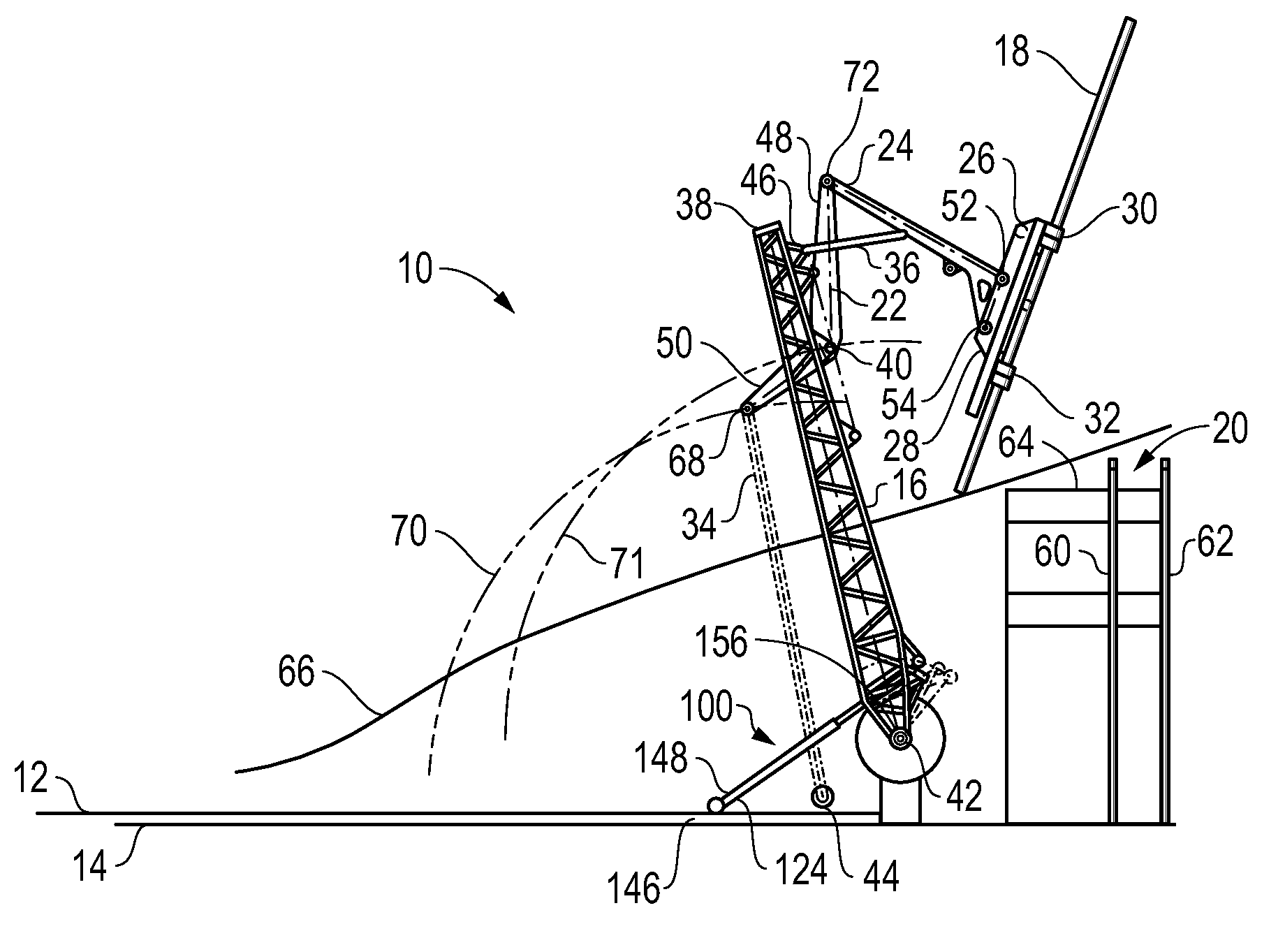
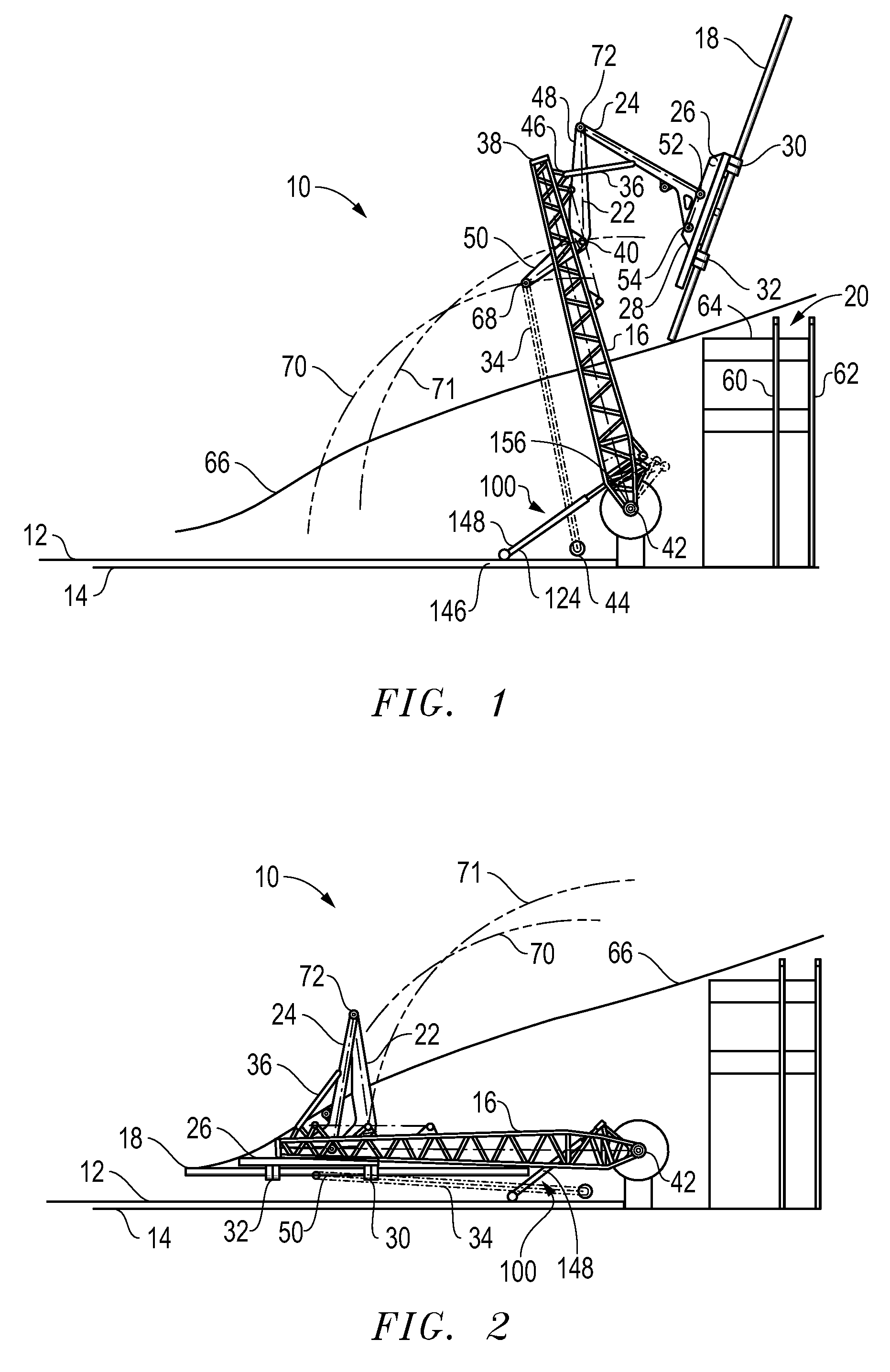
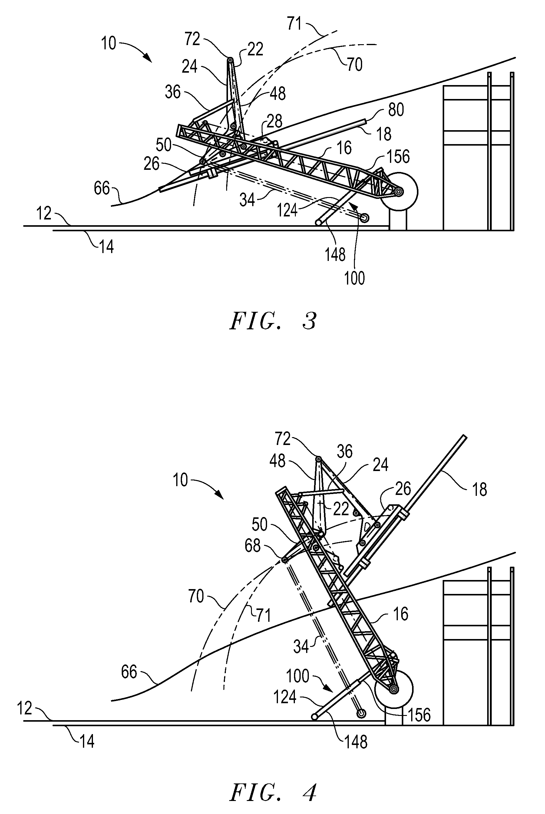
[0043]Referring to FIG. 1, there is shown a side elevational view of the preferred embodiment of the apparatus 100 of the present invention as used with a pipe handling system 10. The pipe handling system 10 is mounted on a frame 12 (such as a skid) that is supported upon the bed 14 of a vehicle, such as a truck. The pipe handling system 10 includes a boom 16 that is pivotally movable between a first position and a second position relative to a frame 12. In FIG. 1, an intermediate position of the pipe handling system 10 is particularly shown. In this position, the pipe 18 is illustrated in its position prior to installation on the drill rig 20. A lever assembly 22 is pivotally connected to the boom 16. An arm 24 is pivotally connected to an end of the lever assembly 22 opposite the boom 16. A gripper 26 is fixedly connected to an opposite end of the arm 24 opposite the lever assembly 22. The gripper 26 includes a stab frame 28 and grippers 30 and 32. A link 34 has one end pivotally ...


PUM


Abstract

The invention relates to a pipe handling apparatus that delivers and positions tubulars at a wellhead and a device for assisting pivotal movement of a boom relative to a base of the apparatus. A pneumatic spring assembly is pivotally connected between the boom and base. During operation, the pneumatic spring assembly urges the boom from a first position to a second position and resists movement of the boom from the second position to the first position. A pneumatic reservoir may be attached to the pipe handling apparatus. A gas-charging assembly fluidically connects the pneumatic spring assembly and pneumatic reservoir and allows the pneumatic reservoir to vary the pneumatic pressure within the pneumatic spring assembly. Sensors mounted in the pipe handling apparatus may provide feedback to a controller which may automatically adjust the amount of pneumatic pressure within the pneumatic springs for ideal performance of the springs.

Description

CROSS-REFERENCE TO RELATED APPLICATIONS[0001]This application is a continuation-in-part of and claims the benefit of priority to application Ser. No. 12 / 418,302, filed Apr. 3, 2009, now U.S. Pat. No. 8,172,497.FIELD OF THE INVENTION[0002]The present invention relates to the delivery of tubulars from a horizontal orientation to a vertical orientation at a well head. Particularly, the present invention relates to a pipe handling apparatus that positions tubulars at a wellhead. More particularly, the present invention relates to a device for assisting pivotal movement of a boom relative to a base of a pipe handling apparatus.BACKGROUND OF THE INVENTION[0003]Drill rigs have utilized several methods for transferring tubular members from a pipe rack adjacent to the drill floor to a mousehole in the drill floor or the well bore for connection to a previously transferred tubular or tubular string. The term “tubular” as used herein includes all forms of pipe, drill pipe, drill collars, casin...

Claims


Application Information

Patent Timeline
Patent Type & Authority Applications(United States)
IPC IPC(8): E21B19/15
CPCE21B19/155B23P19/10Y10S901/48Y10S414/126
Inventor ORGERON, KEITH J.SIGMAR, AXEL M.
Owner SCHLUMBERGER TECH CORP
Why Eureka
Try Eureka