
Elevator

Active Publication Date: 2012-11-08
WOBBEN ALOYS
View PDF18 Cites 12 Cited by
  • Summary
  • Abstract
  • Description
  • Claims
  • Application Information

AI Technical Summary

Benefits of technology

[0007]Therefore one object of the present invention is to reduce the costs of the lift and thus make the lift economically more attractive.
[0011]For that purpose in the first position the connection is made between the drive unit and the lift car in the operating position so that all of the internal space in the lift car is available for transporting freight and / or people while in the second vertically displaced position the drive unit is held in a lowered position in the lift car, which saves on transport space.
[0012]The change between the transport position and the operating position only involves releasing the connection between the drive unit and the lift car, moving the drive unit into the desired position and restoring or tightening the connection in the correspondingly different position. There is no need for further interventions. In that way the change between the transport position and the operating position can be effected very easily and with a time saving.
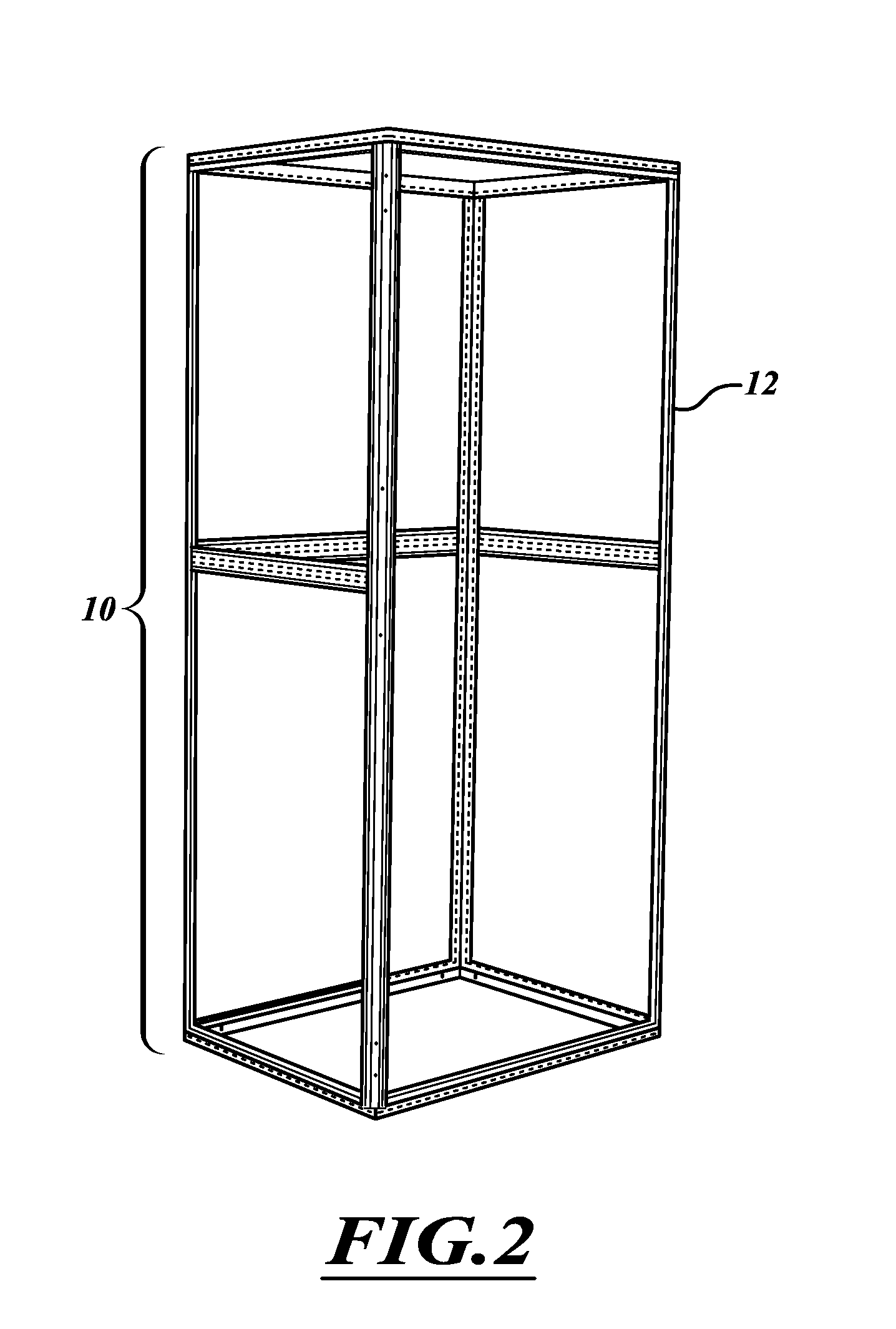
[0015]A further possible way of cost savings is afforded if, instead of a particular lift car, a cupboard which is usually employed as a switch cabinet is used as the car for a lift. Switch cabinets can be produced in large numbers at lower cost, they can be used as cars for lifts and they can be easily adapted to the particular demands involved as a car for a lift so that the cost advantage is also not lost as a result of that.

Problems solved by technology

That makes it unnecessary for example for maintenance engineers who have to perform operations in the pod of the wind power installation to make a strenuous and time-consuming climb by way of the ladders which generally lead perpendicularly upwardly in the pylon.
In the case of wind power installations with hub heights of about 140 m which are not unusual nowadays, that would more specifically involve a vertical climb up (and naturally also a subsequent climb down) over precisely that distance of 140 m. If it is further considered that a maintenance team may be active in a number of wind power installations in the course of a working day, it will quickly be clear that using the ladders can involve an extreme physical stress.
As a result the lifts are becoming more and more a cost factor because they no longer occur occasionally in wind power installations.

Method used


Image

  • Elevator
  • Elevator
  • Elevator

Examples


Embodiment Construction

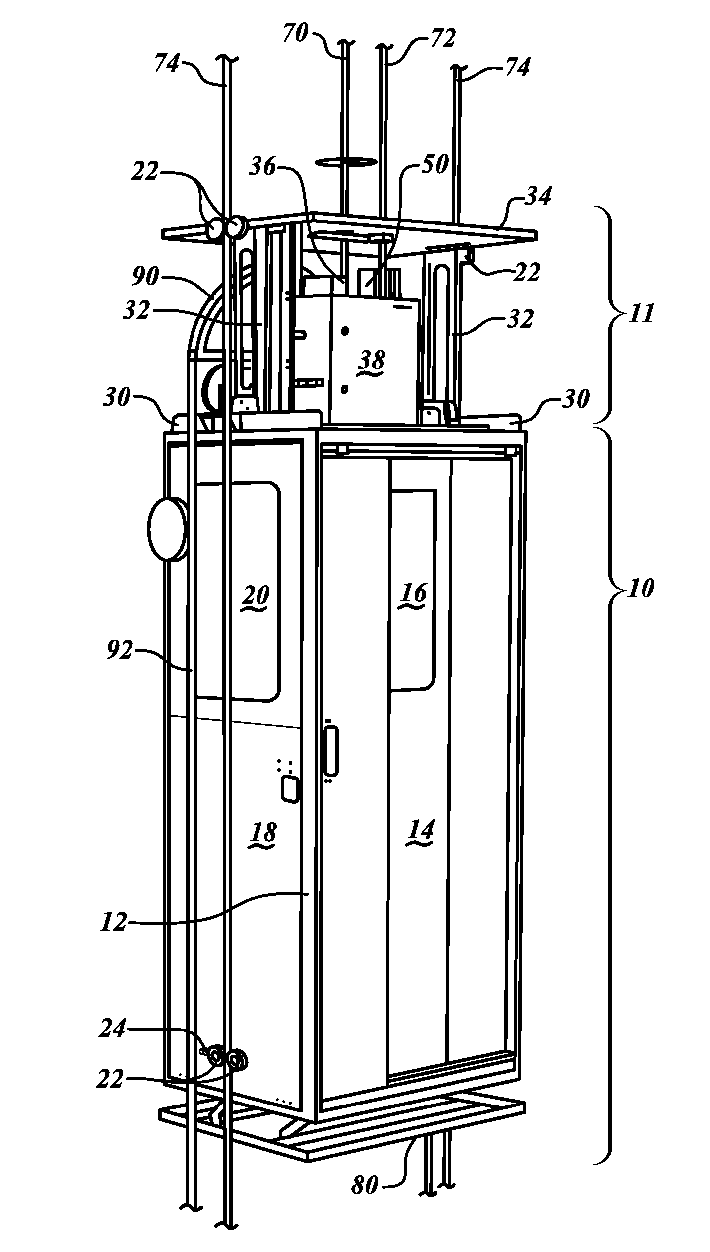
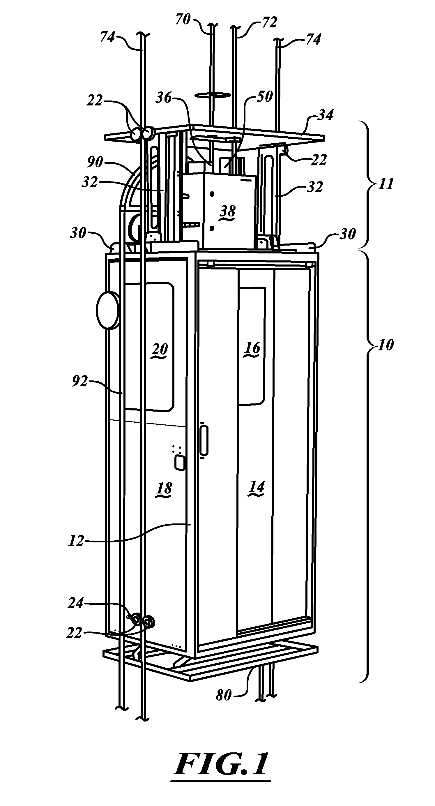
[0029]FIG. 1 shows the complete lift with the lift car 10 and the drive unit 11. The lift car 10 substantially includes a switch cabinet body 12 as a load-bearing structure. Fitted into that switch cabinet body 12 is a sliding door 14 in which a window 16 is in turn provided. Side portions and naturally a rear wall (not shown in this Figure) are also installed. The side portion 18 having a window 20 can be clearly seen in this Figure.

[0030]In addition, shown at the left-hand side which is visible in this Figure are guide cable rollers 22 for the guide cable 74 and a carrier cable guide 24 through which the carrier cable 70 is guided. Corresponding guide cable rollers are disposed on the opposite side of the lift car 10 according to the invention, that side however is not shown in this Figure. There, there is also a catch cable guide (also not shown in this Figure) for the catch cable 72 which holds the lift car for example upon failure of the normal lift drive.

[0031]Holders 30 are m...


PUM


Abstract

The invention concerns a lift having a drive unit. The invention further concerns a wind power installation having a lift. To reduce the costs of the lift and thus make the lift economically more attractive the lift of the kind set forth in this specification is characterized by a cupboard used as the lift car. In that respect the invention is based on the realization that a cupboard in its basic structure with bottom, side walls and a door does not differ from a lift car produced specifically for a lift. Naturally there are differences, for example in suspension and operation of the door, but those differences can be removed insofar as they are an obstacle to use of a cupboard as a lift car so that the complication and expenditure overall is always still less than the complication and expenditure for a lift car constructed specifically for the lift.

Description

BACKGROUND[0001]1. Technical Field[0002]The present invention concerns a lift having a drive unit. The invention further concerns a wind power installation having a lift.[0003]2. Description of the Related Art[0004]Nowadays lifts, also called elevators, are usual in particular in large wind power installations for transporting people and material. That makes it unnecessary for example for maintenance engineers who have to perform operations in the pod of the wind power installation to make a strenuous and time-consuming climb by way of the ladders which generally lead perpendicularly upwardly in the pylon. In the case of wind power installations with hub heights of about 140 m which are not unusual nowadays, that would more specifically involve a vertical climb up (and naturally also a subsequent climb down) over precisely that distance of 140 m. If it is further considered that a maintenance team may be active in a number of wind power installations in the course of a working day, ...

Claims


Application Information

Patent Timeline
IPC IPC(8): B66B9/00B66B11/04
CPCY02B50/12B66B11/0226F03D80/50F05B2240/916Y02E10/728Y02B50/00B66B11/02B66B5/0087B66B11/0246B66B11/06B66B9/16
Inventor MEYER, HERMANNNEUNDLINGER, ULRICH
Owner WOBBEN ALOYS
Learn More