Gasket for parabolic ramp self restraining bell joint

a parabolic ramp and bell joint technology, applied in the field of couplings and methods, can solve the problems of bending or deflecting the joints, reducing the acceptance of fittings, valves, hydrants, etc., and achieves the effect of little increase in insertion for

Active Publication Date: 2012-11-08
MUELLER INT LLC
View PDF2 Cites 12 Cited by
  • Summary
  • Abstract
  • Description
  • Claims
  • Application Information

AI Technical Summary

Benefits of technology

[0025]Another embodiment of the disclosure is a method of coupling at least two conduits. The method includes the steps of positioning a sealing device inside a bell coupled to one end of a first conduit, inserting a spigot of a second conduit through the sealing device inside the bell, and partially removing the spigot from the bell. A locking segment of the sealing device engages the outer surface of the spigot as the spigot is partially removed from the bell. The sealing device is adapted to move axially within the bell in the direction of the insertion of the spigot and the movement is assisted by the presence of expansion and contraction grooves in the coupling section of the gasket. This movement allows the locking segment to be displaced from the path of the incoming spigot with little increase in insertion force. The axial movement may be confined to one segment of the sealing device to accommodate angular and radial misalignment of the incoming spigot. The sealing device is adapted to move in the direction of the partially removed spigot from the bell in response to internal hydraulic pressure to effect a seal to the spigot that rests in an angular and radial misaligned position.

Problems solved by technology

There are two related problems in the history of using pipes of any sort, including iron pipe: (1) creating a secure seal to join the pipes and to withstand large pressures, and (2) bending or deflecting the joints of the pipes to meet the intended use of the pipes.
Flanged joint systems are costly to install and require considerable maintenance.
While the push-on type joint has obtained wide acceptance for pipe joints, acceptance for fittings, valves, and hydrants is much lower.
Whether the pipe end is produced in a manufacturing plant or is the result of field cuts required to adjust the length of the pipe, it is not practical to have beveled or rounded ends in such pipes.
Damage to the gaskets or displacement of the gaskets is a likely outcome when inserting a spigot end of a pipe not properly aligned or without a beveled or rounded end into the bell of another push-on joint pipeline component.
Attempts to design low insertion-resistance joints have been made in the past using normal straight-sided conical bell sockets and straight-sided conical gaskets, but these designs were not completely satisfactory because normal conical inner surfaces do not allow for sufficient deflection of the bell and socket joint.
This misalignment can cause irregular engagement of the spigot, inconsistent loading of the gasket, point loads in the bell socket, unlocking of locking segments, and / or broken teeth of the locking segments.

Method used


Image

  • Gasket for parabolic ramp self restraining bell joint
  • Gasket for parabolic ramp self restraining bell joint
  • Gasket for parabolic ramp self restraining bell joint

Examples


example

[0077]An experiment using two lengths of 8 inch pipe was conducted. One pipe had a bell as described herein while the other had a spigot as described herein. The two lengths were joined using a sealing device as described herein. The pipes were sealed at their respective open ends and the internal cavity was pressurized. The experiment was conducted first with the pipes having no deflection and then with the pipes having 5.7° of deflection. The results are compiled in Table 1.

MinimumPressure atTestNo. ofJointPressure,Failure,FailureNumberSegmentsDeflection, °psipsiMode180700772Gasket Tear280700771Gasket Tear31407001192Gasket Tear4100700998.5Gasket Tear5105.7700828.2Gasket Tear6147.5°7001028Gasket Tear

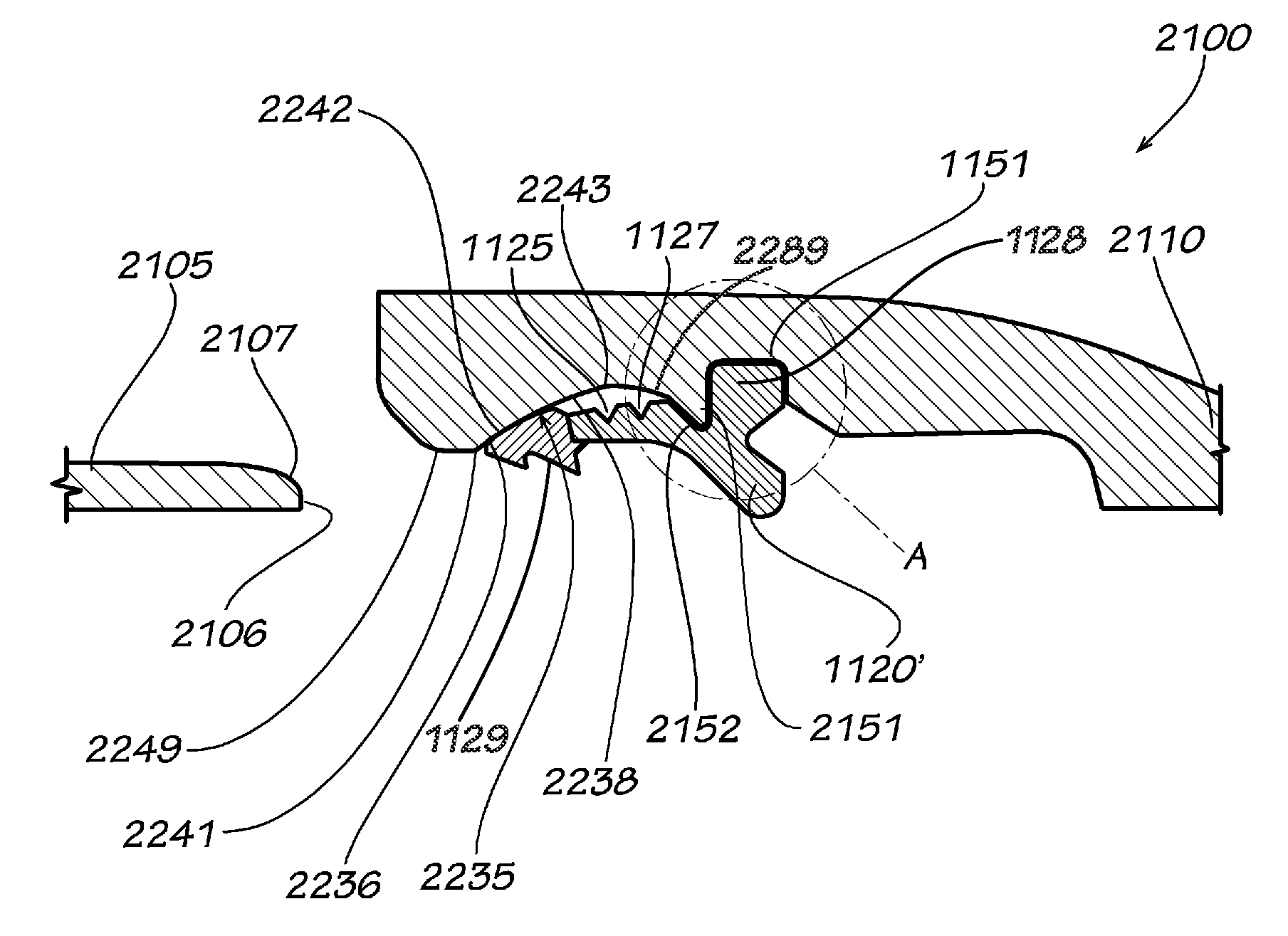
[0078]If “θ” is defined as the angle of deflection between the axis of the bell socket 1010 and the spigot 1005, through moderate angles of deflection, the locking segments 1025 following the major axis of an ellipse projected onto a plane inclined perpendicular to the axis will, on the...


PUM


Abstract

Gaskets for use with a bell and spigot coupling system are disclosed herein. The gasket comprises an elastomeric member having a front edge, a first section, and a second section. Axial forces generated by the insertion of the spigot to the first section of the elastomeric member displace the first section of the elastomeric member in an axial and radial direction.

Description

CROSS-REFERENCE TO RELATED APPLICATION[0001]This application is a continuation-in-part of U.S. patent application Ser. No. 13 / 216,523, filed on Aug. 24, 2011, which claims the benefit of U.S. Provisional Application 61 / 376,450, filed on Aug. 24, 2010, both of which are hereby incorporated by reference herein in their entirety.BACKGROUND[0002]1. Field[0003]The disclosure is directed to couplings and methods of coup g, particularly to bell and spigot couplings and methods.[0004]2. Description of Related Art[0005]Members of the flow control industry, such as producers of pipeline components for the transmission of water, gas, oil, or other fluids have focused substantial attention on the problem of creating and maintaining connections between adjacent lengths of pipe, or pipes and fittings, or pipes and valves. In applications where the fluid, such as water for fire mains or water distribution in municipalities, is under high pressure, various means are used to prevent separation of th...

Claims


Application Information

Patent Timeline
Patent Type & Authority Applications(United States)
IPC IPC(8): F16L21/02
CPCF16L21/03F16L37/0845F16L27/02F16L17/032F16L37/0925
Inventor HOLMES, IV, WILLIAM W.OWEN, WILLIAM H.
Owner MUELLER INT LLC
Why Eureka
Try Eureka