Horizon scanning system for a rotary wing aircraft including sensors housed within a tubercle on a rotor blade

Active Publication Date: 2012-11-08
RAYTHEON CO
View PDF18 Cites 22 Cited by
  • Summary
  • Abstract
  • Description
  • Claims
  • Application Information

AI Technical Summary

Problems solved by technology

The aircraft are expensive t

Method used


Image

  • Horizon scanning system for a rotary wing aircraft including sensors housed within a tubercle on a rotor blade
  • Horizon scanning system for a rotary wing aircraft including sensors housed within a tubercle on a rotor blade
  • Horizon scanning system for a rotary wing aircraft including sensors housed within a tubercle on a rotor blade

Examples


Example

DETAILED DESCRIPTION OF THE DRAWINGS

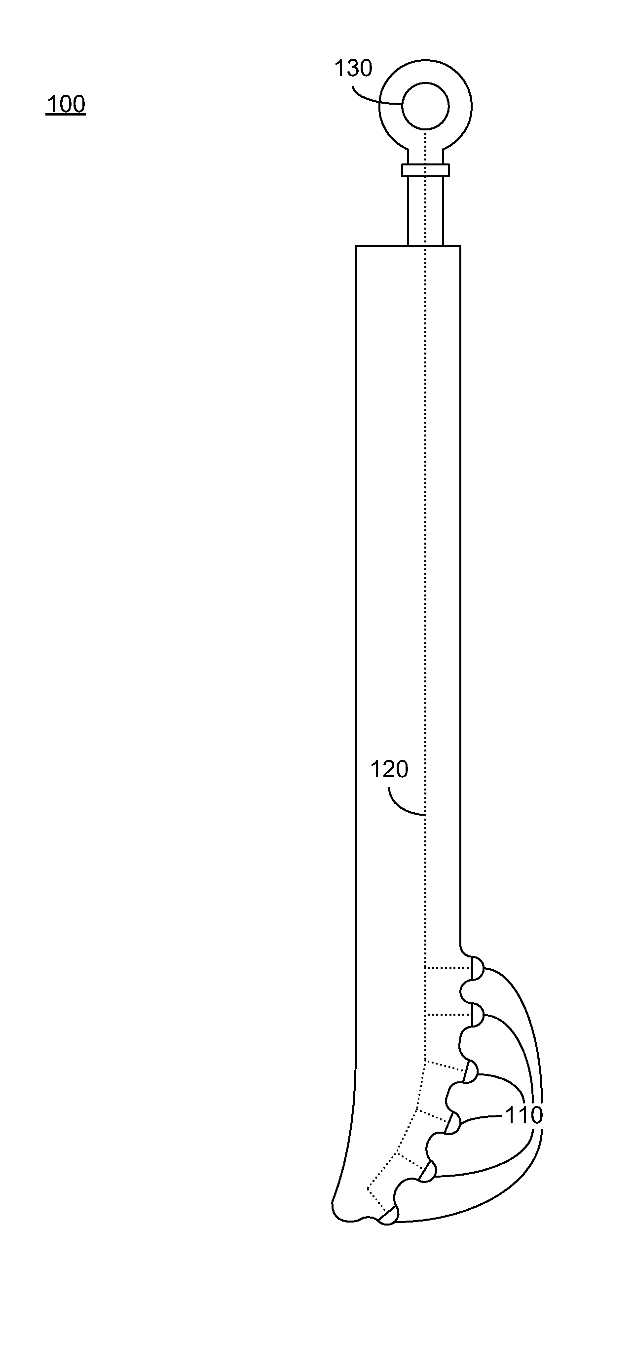
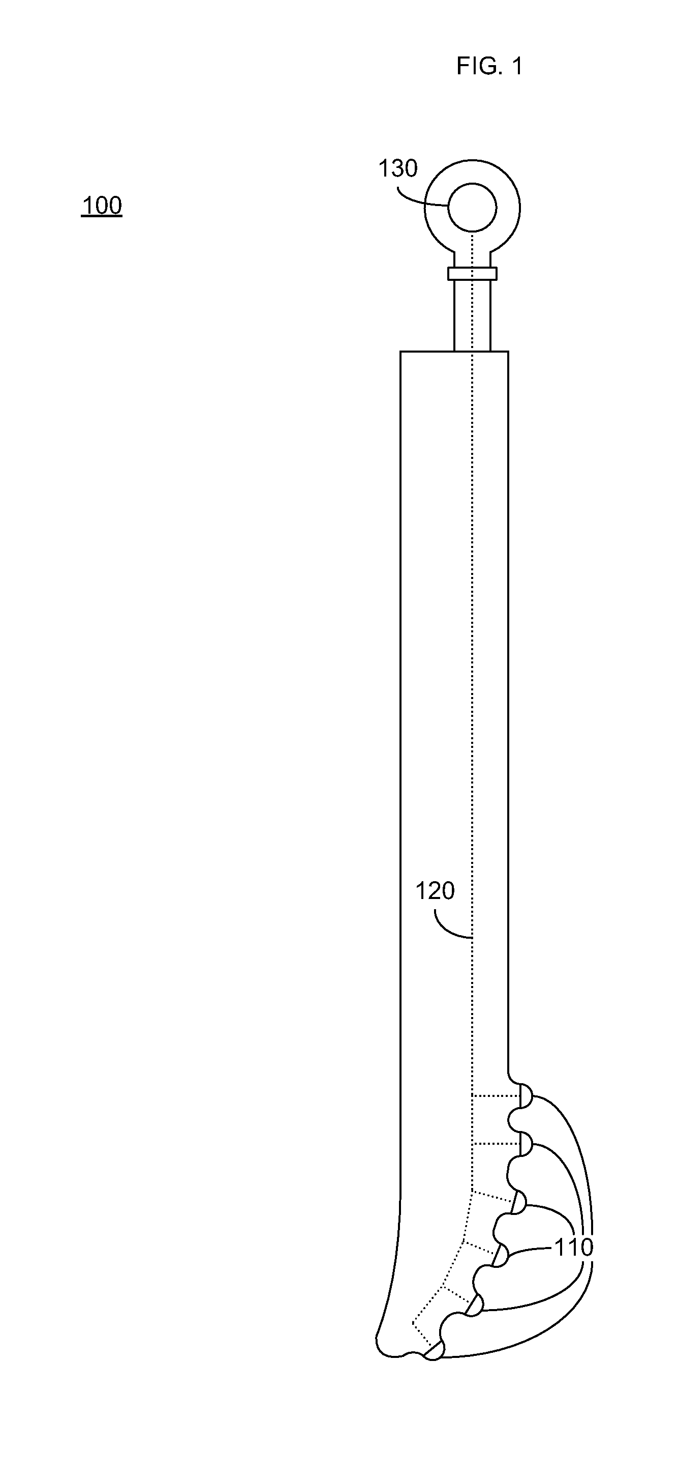
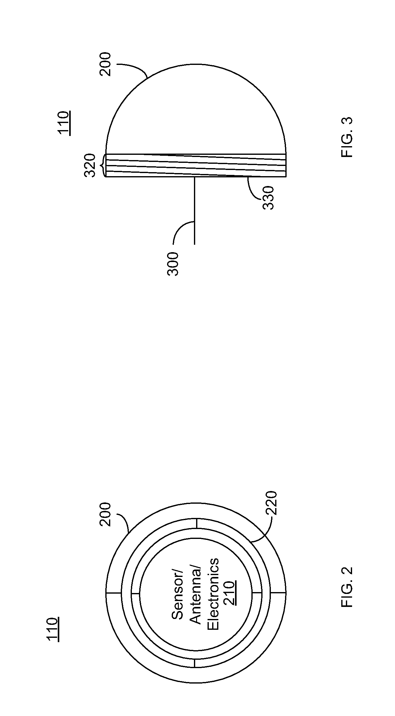
[0014]The following discussion generally relates to a rotary wing aircraft, such as a helicopter, having a horizon scanning system. Because a rotary wing aircraft has a smaller body than the aircraft typically used to perform horizon scanning, the horizon scanning system described herein has a smaller blind spot than the current system. As described in further detail below, the sensors, antennae and support electronics for the horizon scanning system are housed in tubercles placed on the leading edge of the rotary blades of the rotary wing aircraft. The following detailed description is merely illustrative in nature and is not intended to limit the embodiments or the application and uses thereof. Furthermore, there is no intention to be bound by any expressed or implied theory presented in the preceding technical field, background, brief summary, or the following detailed description.

[0015]FIG. 1 illustrates an exemplary rotor blade 100 for a rota...


PUM


Abstract

A rotary wing aircraft, a rotor blade and a horizon scanning system are provided. The rotary wing aircraft, for example, may include, but is not limited to, a mast, an engine configured to provide rotational force to the mast and a controller. The rotary wing aircraft may further include a rotor blade connected to the mast having a leading edge, a plurality of tubercles positioned on the leading edge of the rotor blade, and a sensor housed within at least one of the plurality tubercles communicatively connected to the controller.

Description

TECHNICAL FIELD[0001]Embodiments of the subject matter described herein relate generally to horizon scanning systems on a rotary wing aircraft, and more particularly to using housing sensors, antennae and support electronics in tubercles positioned on a leading edge of the rotors of the rotary wing aircraft.BACKGROUND[0002]Currently, horizon scanning is performed by aircraft having airborne early warning and control (AEWC) systems, which are also known as airborne warning and control systems (AWACs). The aircraft are expensive to build, maintain and repair. Furthermore, the AEWC system is typically mounted on the top of the aircraft. Accordingly, the aircraft body, which is typically quite large, blocks a large portion of the sky, preventing the AEWC system from detecting objects or weather conditions in the aircraft's shadow.[0003]Accordingly, there is a need for improved horizon scanning systems. Other desirable features and characteristics will become apparent from the subsequent...

Claims


Application Information

Patent Timeline
IPC IPC(8): G01S13/95G01S13/88B64C27/00
CPCB64C27/04G01S2007/027B64D47/08B64C27/46G01S7/027
Inventor ELDER, STEVEN J.
Owner RAYTHEON CO
Why Eureka
Try Eureka