Temperature-Independent Capacitor and Capacitor Module

a capacitor module and temperature-independent technology, applied in the direction of variable capacitors, fixed capacitor details, electrical appliances, etc., can solve the problem of increasing power

Inactive Publication Date: 2012-11-08
EPCOS AG
View PDF3 Cites 23 Cited by
  • Summary
  • Abstract
  • Description
  • Claims
  • Application Information

AI Technical Summary

Benefits of technology

[0005]The intention is thereby to avoid a change in the dielectric constant of the dielectric material of the ca...

Problems solved by technology

A widespread problem in respect of c...

Method used


Image

  • Temperature-Independent Capacitor and Capacitor Module
  • Temperature-Independent Capacitor and Capacitor Module
  • Temperature-Independent Capacitor and Capacitor Module

Examples


Embodiment Construction

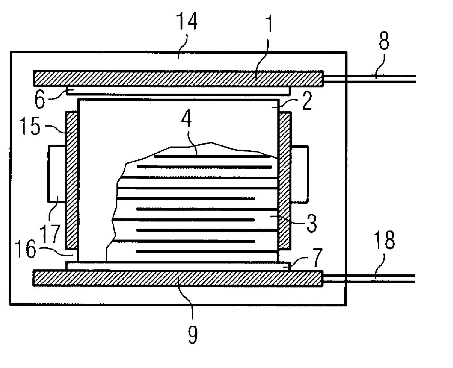
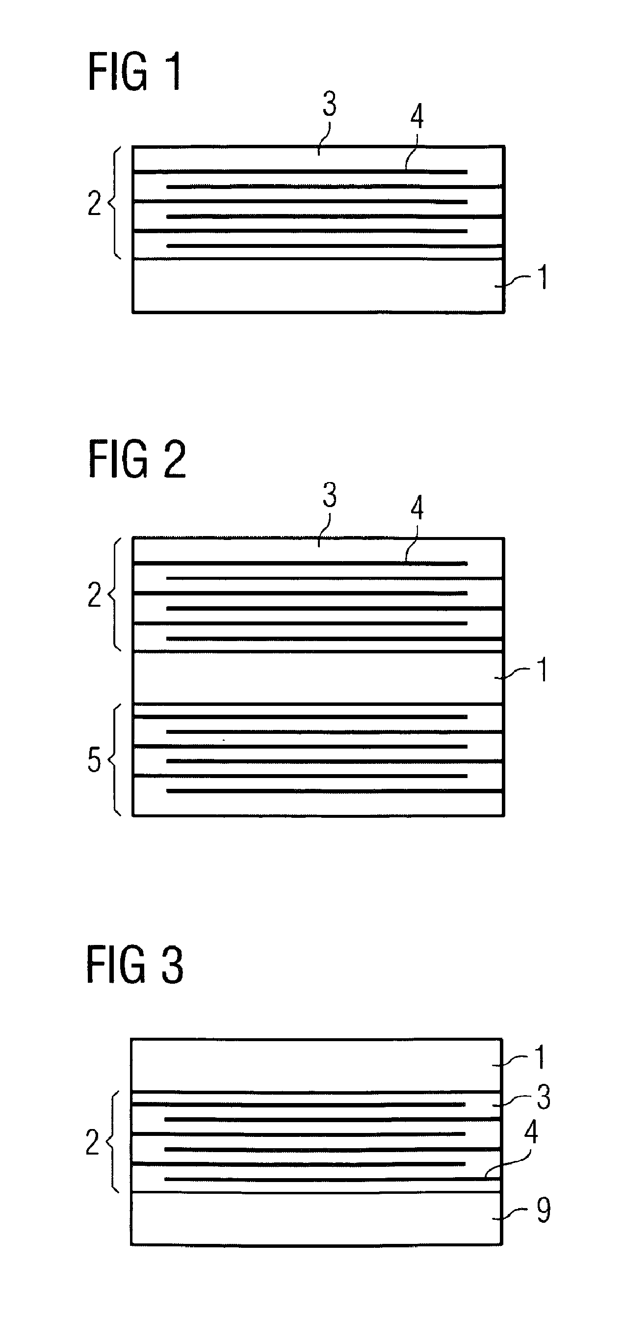
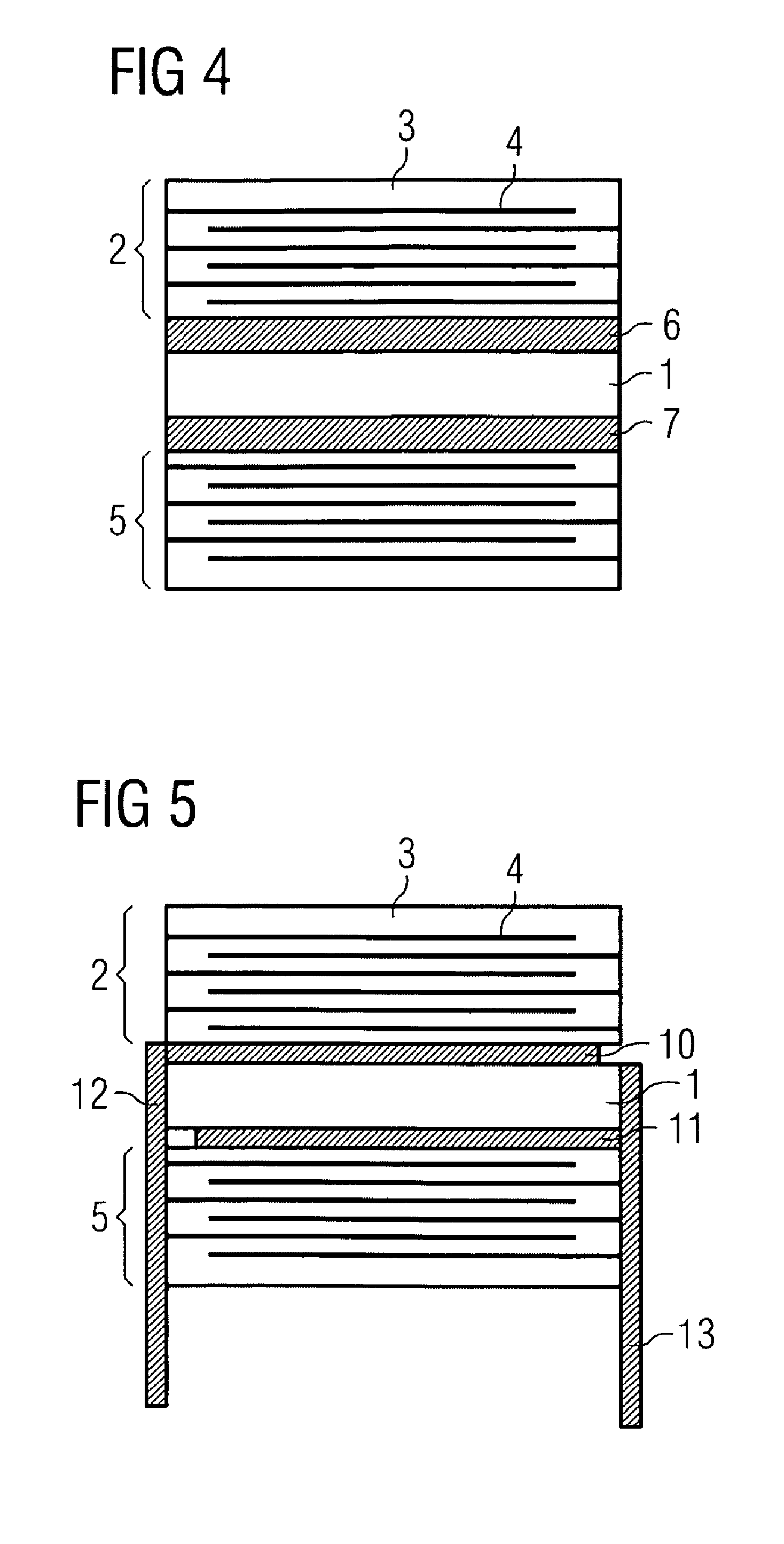
[0073]FIG. 1 illustrates an exemplary embodiment comprising a first heating element 1, on which a first capacitor region 2 is arranged. The first capacitor region 2 comprises dielectric layers 3, between which the internal electrodes 4 are arranged. As a result of the direct contact of the first heating element 1 and of the first capacitor region 2, the heat generated in the first heating element 1 can be transmitted directly to the first capacitor region 2, as a result of which, by way of example, the dielectric constant of the dielectric layers 3 can be increased, which leads to an increase in the power of the capacitor. For this purpose, a material whose dielectric constant increases as the temperature increases is used for the dielectric layers 3. This applies at least to the temperature range to which the first heating element 1 can be heated. Materials for dielectric layers can comprise ferroelectric or antiferroelectric materials. This also applies to the dielectric layers in...


PUM

PropertyMeasurementUnit
Temperatureaaaaaaaaaa
Dielectric polarization enthalpyaaaaaaaaaa
Electrical resistanceaaaaaaaaaa

Abstract

A capacitor includes a first heating element and a first capacitor region. The first capacitor region includes dielectric layers and internal electrodes. The internal electrodes are arranged between the dielectric layers. The first heating element and the first capacitor region are connected to each other in a thermally conductive manner.

Description

[0001]This patent application is a national phase filing under section 371 of PCT / EP2010 / 070426, filed Dec. 21, 2010 (WO 2011 / 085932 published Jul. 21, 2011), which claims the priority of German patent application DE 102009059879.0, filed Dec. 21, 2009, each of which is incorporated herein by reference in its entirety.TECHNICAL FIELD[0002]The present invention relates a temperature-independent capacitor and capacitor module.BACKGROUND[0003]A widespread problem in respect of capacitors is increasing the power thereof.[0004]Hitherto, the problem has been solved by arranging dielectric materials having different dopings in successive layer sequences, for example as core and sheath. In conventional capacitors, materials whose dielectric constants are largely independent of temperature in a wide range are generally used for the dielectric materials.SUMMARY OF THE INVENTION[0005]The intention is thereby to avoid a change in the dielectric constant of the dielectric material of the capacit...

Claims


Application Information

Patent Timeline
IPC IPC(8): H01G2/08H01G4/258
CPCY10T29/43H01G4/258
Inventor ENGEL, GUENTERTESTINO, ANDREASCHOSSMANN, MICHAELKOINI, MARKUSHOFFMANN, CHRISTIAN
Owner EPCOS AG
Why Eureka
Try Eureka