Controlled evacuation ostomy appliance

a technology of ostomy and controlled discharge, which is applied in the field of ostomy appliances, can solve problems such as design complexity, and achieve the effect of enhancing the usefulness of the applian

Active Publication Date: 2012-11-08
CONVATEC TECH INC
View PDF8 Cites 61 Cited by
  • Summary
  • Abstract
  • Description
  • Claims
  • Application Information

AI Technical Summary

Benefits of technology

[0004]The present invention appreciates that further improvements to the above design of ostomy appliance may enhance yet further the advantages and usefulness of the appliance for an ostomate.
[0008]In some embodiments of the invention, the stoma seal is positioned relative to the stomal aperture such that, in use and with a stoma in a quiescent or rest state, the stoma seal just touches the stoma and / or exerts a seal pressure on the stoma of not more than about 1 psi (51.7 mm Hg). When the stoma becomes active, the force of stool within the intestine urges the stoma outwardly against the stoma seal. The stoma seal resists by applying a reaction pressure against the outwardly urged stoma. The stoma seal is supported in position by the inner coupling member. The stoma seal exerts a seal pressure on the stoma not more than about 2 psi (103.4 mm Hg) when the stoma becomes active. Such an arrangement takes advantage of the fact that when the stoma is at rest, little or no seal effect is needed against the stoma. The stoma seal has little contact and / or seal pressure against the stoma, avoiding any concerns of prolonged application of significant sealing pressure applied to the stoma tissue. Yet the stoma seal is supported by the inner coupling member, and is able to withstand outward challenges from the stoma by applying a reactive sealing pressure.
[0010]Additionally or alternatively, in some embodiments of the invention, the stoma seal is resiliently deformable, and is configured to generate a reaction pressure of not more than about 2 psi (preferably not more than about 1 psi, preferably not more than about 0.8 psi) when the stoma seal is compressed or deflected. The amount of stoma seal compression could be at least 5%, or preferably, at least 10%. Such a relatively soft stoma seal can provide excellent conformity to closely follow the contour of the stoma, without risk of exerting excessive force.
[0017]Such an arrangement can provide increased collection volume for the lower portion of the pouch and / or reduce the length of distension to achieve a desired collection volume. The reduced width of the lower portion (with the side region(s) folded inwardly) may optionally have substantially the same width as the upper region or necked region, as appropriate. The reference to “substantially the same width” means to within about 2 cm and / or 20% of the width.
[0018]Additionally or alternatively, in some embodiments, the appliance further comprises a flexible cover that substantially covers the second wall in the upper region of the pouch. The flexible cover includes an integral retainer for retaining the lower portion of the pouch in the folded-up configuration. The flexible cover may optionally be made from a rubber or thermoplastic elastomer to provide a soft, comfortable and impact absorbing surface.

Problems solved by technology

There are conflicting requirements for the seal that complicate the design.

Method used


Image

  • Controlled evacuation ostomy appliance
  • Controlled evacuation ostomy appliance
  • Controlled evacuation ostomy appliance

Examples


second embodiment

[0065]The main differences with the second embodiment are:

first embodiment

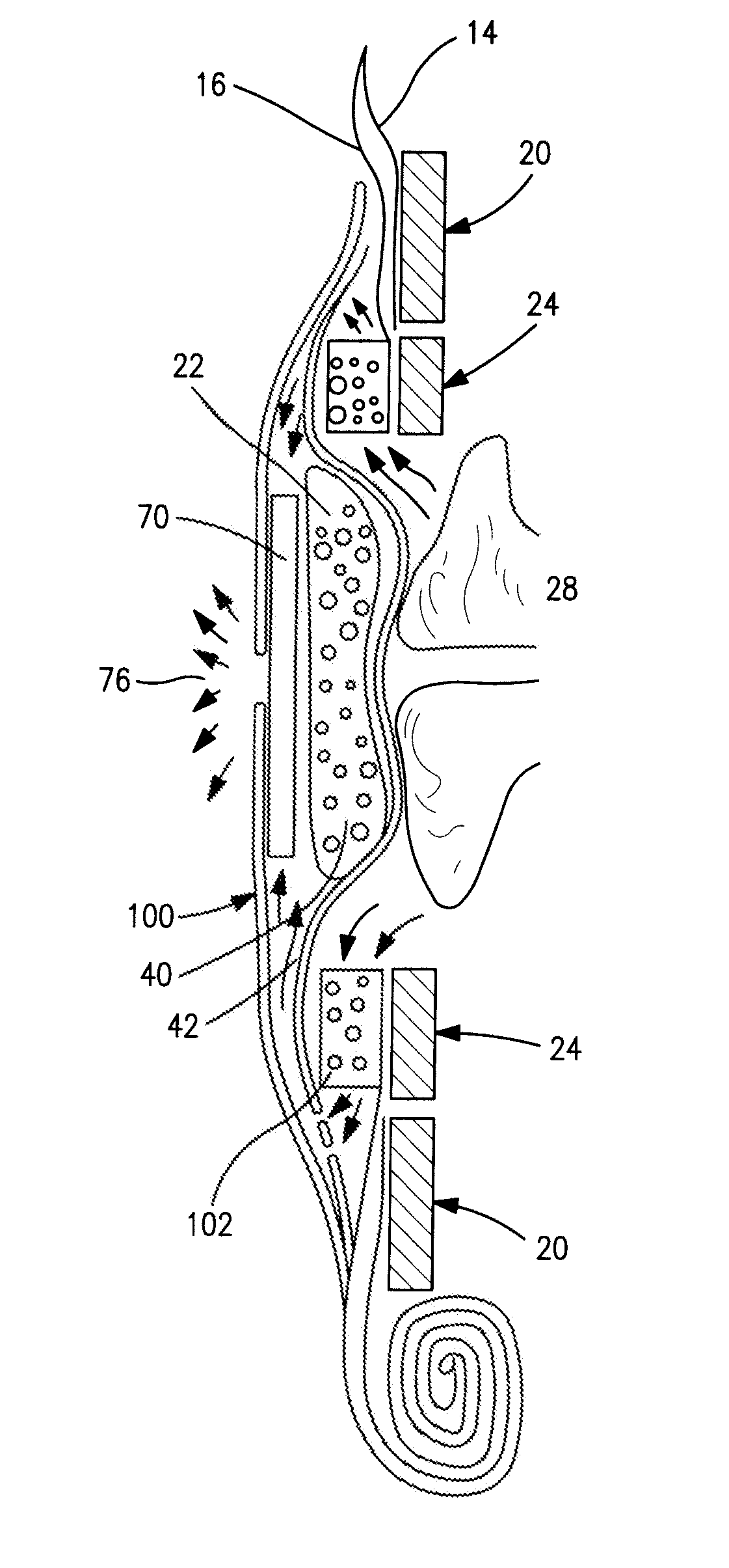
[0066](i) The seal holder 60 and cover 80 of the first embodiment are replaced by a combined holder / cover 100, to which the seal membrane 42 is attached. The holder / cover 100 is attached to the second (front) wall 16 at a position outside the attachment of the second wall 16 to the second coupling member 24. A portion of the second wall 16 extending between the second coupling member 24 and the holder / cover 100 therefore acts as a form of pressure relieving suspension for the stoma seal 22. Should the pressure exerted by the stoma seal 22 on the stoma 28 exceed a threshold, the wall material of the second wall 16 will flex, allowing the stoma seal 22 to float partially with respect to the second coupling member 24, and thereby relieve excess seal pressure on the stoma.

[0067]An annular foam member 102 circumscribing the seal 22 acts as a phase separator allowing flatus to pass therethrough to the deodorizing filter 70, while obstructing passage of any solid or semi-liquid stool that ...


PUM


Abstract

A controlled evacuation ostomy appliance comprises a pouch having a non-entrant stoma seal and a retainer for retaining the lower portion of the pouch in the folded-up condition. The appliance optionally includes a body fitment that may include a region of manually moldable adhesive for forming a custom fit at the stoma.

Description

FIELD OF THE INVENTION[0001]The present invention relates to an ostomy appliance for managing effluent from a stoma. Some aspects of the invention relate to a controlled discharge ostomy appliance. Some aspects of the invention relate to appliance with an external stoma seal. Some aspects of the invention relate to an appliance with an integral waste collector. Some aspects of the invention relate to a prosthetic ostomy appliance.BACKGROUND TO THE INVENTION[0002]WO-A-2008 / 141180 (the content of which is incorporated herein by reference in its entirety) describes a controlled discharge ostomy appliance comprising a pouch having first and second walls, with an inlet aperture in the first wall. A stoma seal is carried by the second wall, and is disposed generally in register with the inlet aperture for sealing against a stoma in use. An outer coupling element is coupled to the first wall and surrounds the inlet aperture. An inner coupling element for supporting the stoma seal, is coupl...

Claims


Application Information

Patent Timeline
Patent Type & Authority Applications(United States)
IPC IPC(8): A61F5/448A61F5/449A61F5/445
CPCA61F5/445A61F5/441A61F5/4404A61F5/443A61F5/448
Inventor NGUYEN-DEMARY, TINHTSAI, MINGLIANG LAWRENCE
Owner CONVATEC TECH INC
Why Eureka
Try Eureka