Method of manufacturing co-molded inserts

a technology of co-molded inserts and manufacturing methods, which is applied in the direction of electric/magnetic/electromagnetic heating, instruments, chemistry apparatuses and processes, etc., can solve the problems of increasing labor costs, requiring a large number of parts and associated logistics, and requiring significant production lead time, so as to reduce costs, reduce costs, and reduce tooling costs or lead time.

Active Publication Date: 2013-02-26
THE BOEING CO
View PDF13 Cites 88 Cited by
  • Summary
  • Abstract
  • Description
  • Claims
  • Application Information

AI Technical Summary

Benefits of technology

[0006]This need for a method of manufacturing co-molded inserts is satisfied. None of the known methods and systems provide all of the numerous advantages discussed herein. Unlike known methods and systems, embodiments of the method of the disclosure may provide one or more of the following advantages: provides a method that uses additive manufacturing to create co-molded inserts for use in composite, plastic, or metal parts; provides a method that allows for co-molded inserts to be created with little or no associated tooling costs or lead time, with reduced costs due to less materials used, with reduced labor time and costs for insert placement, with reduced scrap through higher insert placement precision, and with reduced costs to manufacture inserts in low volumes; provides a method that allows for more advanced, three-dimensional designs of greater geometric complexity to be created with higher precision due to the free form nature of additive manufacturing of inserts; provides a method that creates co-molded inserts in useful materials, such as titanium alloys, thermoplastics, thermoset plastics, and other suitable materials, for use as subcomponents in fiber reinforced or thermoformed plastic parts; provides a method that reduces or eliminates molding, forming, tooling, curing, or machining tools and fixtures to create inserts; provides a method that does not require jigs, fixtures, or laser projection type guides for precise placement of inserts; provides a method that combines multiple parts and inserts into a single, self-positioning piece or unit with minimal connecting geometry to allow for precise placement with low labor requirements; provides a method that improves mechanical performance; provides a method that produces inserts and hardware via a tool-less process to avoid supply chain delays, as parts can be made on demand, in low quantities; provides a method for making co-molded inserts of an integrated design that can lower vehicle weight and can increase assembly accuracy which, in turn, can contribute to better product performance; and provides a method for making composite, plastic, and metal parts having co-molded inserts for use in spacecraft, aircraft, military craft, automobiles, watercraft, and other vehicles and craft.

Problems solved by technology

Known methods and systems for making such molded or assembled inserts may require molding, forming, casting, tooling, and / or curing operations, as well as machining tools and fixtures to create such inserts, and this can be costly and require significant production lead time.
Moreover, molded inserts for use in fiber reinforced plastic parts are normally made individually, thus requiring a large number of parts and associated logistics.
Known methods and systems may require individually molded or machined inserts to be assembled piecemeal, which can introduce precision errors and can result in increased labor costs.
In addition, known methods for manually assembling molded or co-molded inserts can lack precision, as the precise assembly of such inserts typically requires fixtures, jigs, or laser projection type guides to position, place, and bond such inserts to the plastic part precisely.
The use of such fixtures for precise assembly can be costly and time consuming.
In addition, known methods and systems can impose geometric limitations on the design of such molded or co-molded inserts.
None of the known methods and systems provide all of the numerous advantages discussed herein.

Method used


Image

  • Method of manufacturing co-molded inserts
  • Method of manufacturing co-molded inserts
  • Method of manufacturing co-molded inserts

Examples


Embodiment Construction

[0020]Disclosed embodiments will now be described more fully hereinafter with reference to the accompanying drawings, in which some, but not all of the disclosed embodiments are shown. Indeed, several different embodiments may be provided and should not be construed as limited to the embodiments set forth herein. Rather, these embodiments are provided so that this disclosure will be thorough and complete and will fully convey the scope of the disclosure to those skilled in the art.

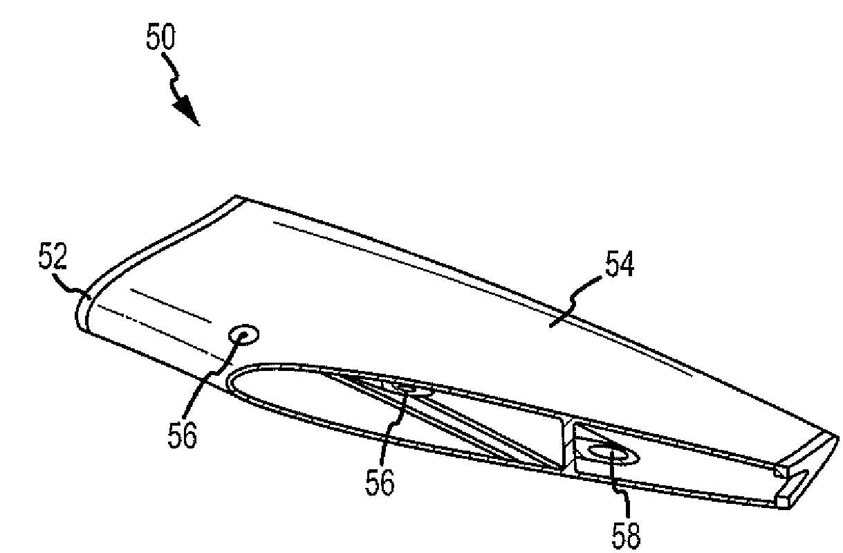
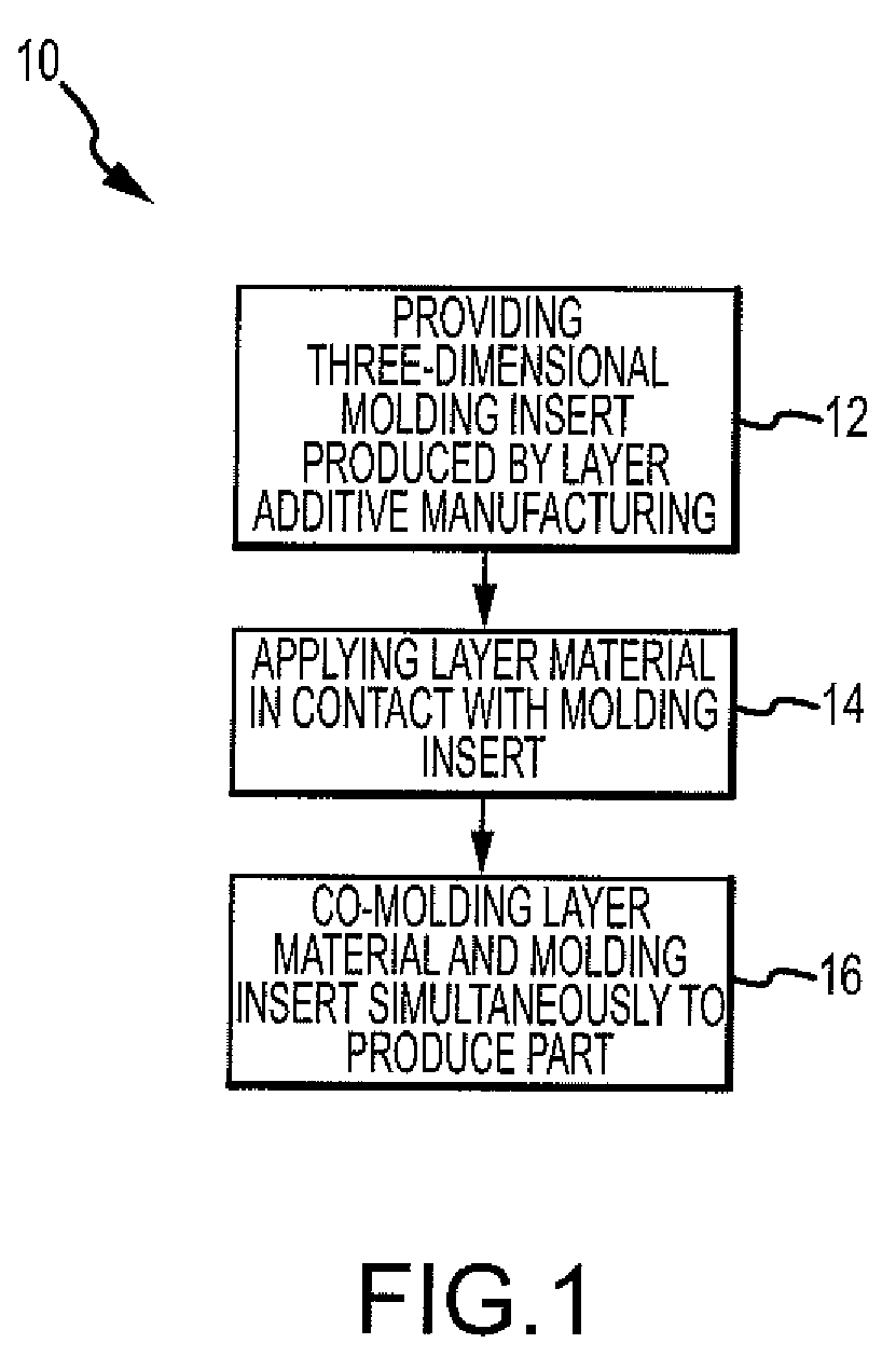
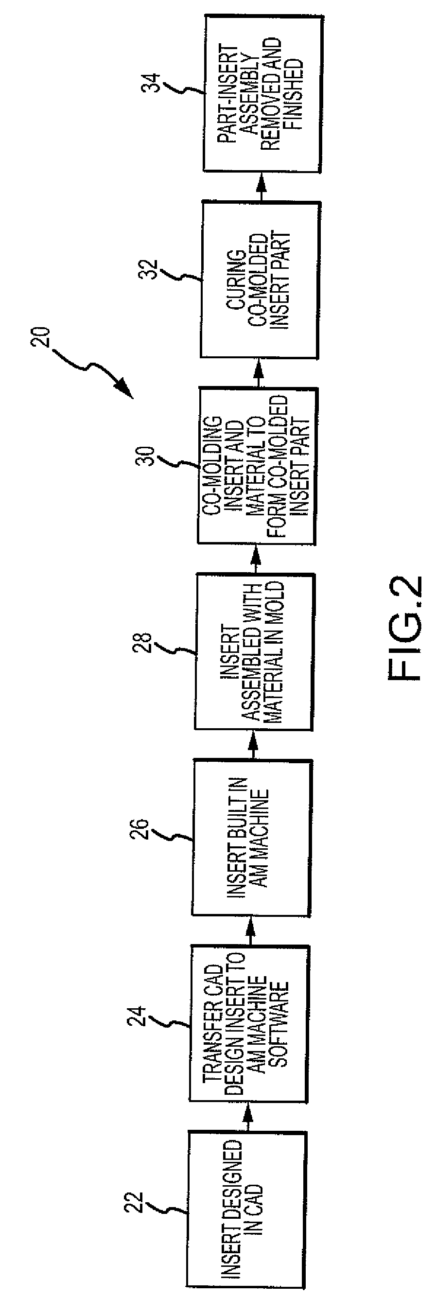
[0021]The method of the disclosed embodiments uses additive manufacturing (AM) technology to make co-molded inserts for use in composite, plastic, and metal part manufacturing or on reinforced or monolithic polymeric parts. The method of the disclosed embodiments may be used for making composite, plastic, and metal parts having co-molded inserts for use in spacecraft, aircraft, military craft, automobiles, watercraft, and other vehicles and craft. Accordingly, one of ordinary skill in the art will recogniz...


PUM

PropertyMeasurementUnit
lengthaaaaaaaaaa
stiffnessaaaaaaaaaa
moldingaaaaaaaaaa

Abstract

A method for manufacturing a co-molded insert part for use in composite, plastic, or metal parts is disclosed. The method comprises the step of providing a three-dimensional molding insert produced by a layer additive manufacturing process. The method further comprises the step of applying a layer material in contact with at least a portion of the molding insert. The method further comprises the step of co-molding the layer material and the molding insert simultaneously to produce a co-molded insert part.

Description

BACKGROUND[0001]1) Field of the Disclosure[0002]The disclosure relates to a method of manufacturing co-molded inserts. In particular, the disclosure relates to a method of manufacturing co-molded inserts for use in composite, plastic, and metal parts using additive manufacturing.[0003]2) Description of Related Art[0004]Composite, plastic, and metal parts can be used in the manufacture of spacecraft, aircraft, military craft, automobiles, watercraft, and other vehicles and craft. Creating geometrically complex, high performance, three-dimensional composite, plastic, or metal parts typically requires multiple sets of tooling and molding operations. Such composite, plastic, or metal parts also typically require assembly with molded inserts made of other materials for joining or system integration, such as wiring or hydraulic brackets. Known methods and systems for making such molded or assembled inserts may require molding, forming, casting, tooling, and / or curing operations, as well a...

Claims


Application Information

Patent Timeline
Patent Type & Authority Patents(United States)
IPC IPC(8): B29B13/00
CPCB29C67/0051B29C70/68Y10T156/1052B33Y80/00
Inventor LYONS, BRETT I.
Owner THE BOEING CO
Why Eureka
Try Eureka