Control system for an electric machine

a control system and electric machine technology, applied in the direction of multiple motor speed/torque control, dynamo-electric machines, synchronous motor starters, etc., can solve the problems of power and efficiency of motors, affecting the operation speed of motors, and negligible phase difference between the detected position and the actual position of the rotor, so as to achieve relatively narrow operating speed range, good performance, and good performance

Active Publication Date: 2010-10-07
DYSON TECH LTD
View PDF31 Cites 35 Cited by
  • Summary
  • Abstract
  • Description
  • Claims
  • Application Information

AI Technical Summary

Benefits of technology

[0010]The operating speed range extends between a minimum speed and a maximum speed, and the minimum speed is at least 80% of the maximum speed. The operating speed range is thus relatively narrow. As a result, the discrepancy between the position-sensor offset and the phase difference at each end of the operating range is relatively small, and thus relatively good performance is achieved over the full operating range.
[0011]Preferably, the operational speed range has a minimum speed greater than 60 krpm. More preferably, the operational speed range has a maximum speed greater than 80 krpm. At these speeds, any misalignment of the position sensor may significantly impact the performance of the electric machine. By correcting the timing of the control signals using a fixed-time offset, good performance can be achieved for a high-speed electric machine.
[0012]Advantageously, the drive controller generates control signals in synchrony with the edges when the electric machine operates over a first speed range, and generates control signals at times relative to the edges and corrected by the position-sensor offset when the electric machine operates over a second higher speed range. The operating speed range of the electric machine then lies within the second speed range. By generating control signals in synchrony with the edges of the signal, control of the electric machine over the lower speed range is simplified. In particular, no correction to the timing of the control signals is required. At low speeds, any phase difference in the signal of the position sensor is unlikely to impact significantly on the performance of the electric machine. Additionally, the time spent by the electric machine in the first lower speed range is likely to be small, e.g. as the electric machine accelerates into the second speed range. Accordingly, in spite of the simplified control, the performance of the electric machine is not adversely affected.
[0013]The control system may drive the electric machine within one of a plurality of operating speed ranges. The drive controller then stores a plurality of position-sensor offsets, each position-sensor offset corresponding to a respective operating speed range. In response to an input signal, the control system drives the electric machine within one of the plurality of operating speed ranges and the drive controller generates control signals at times corrected by the respective position-sensor offset. The control system then provides optimised performance for each of a plurality of different operating ranges.

Problems solved by technology

This tolerance in alignment results in a phase difference between the detected position and the actual position of the rotor.
As a result, phase excitation and rotor position are not perfectly synchronised and thus the power and efficiency of the motor are compromised.
This may be because the circumference of the rotor is relatively large and thus any tolerance in the alignment of the sensor results in a negligible phase difference between the detected and actual positions of the rotor.
However, for electric machines that are relatively small and / or where relatively high efficiency is required, tolerances in the alignment of the sensor present a significant problem.

Method used


Image

  • Control system for an electric machine
  • Control system for an electric machine
  • Control system for an electric machine

Examples


Embodiment Construction

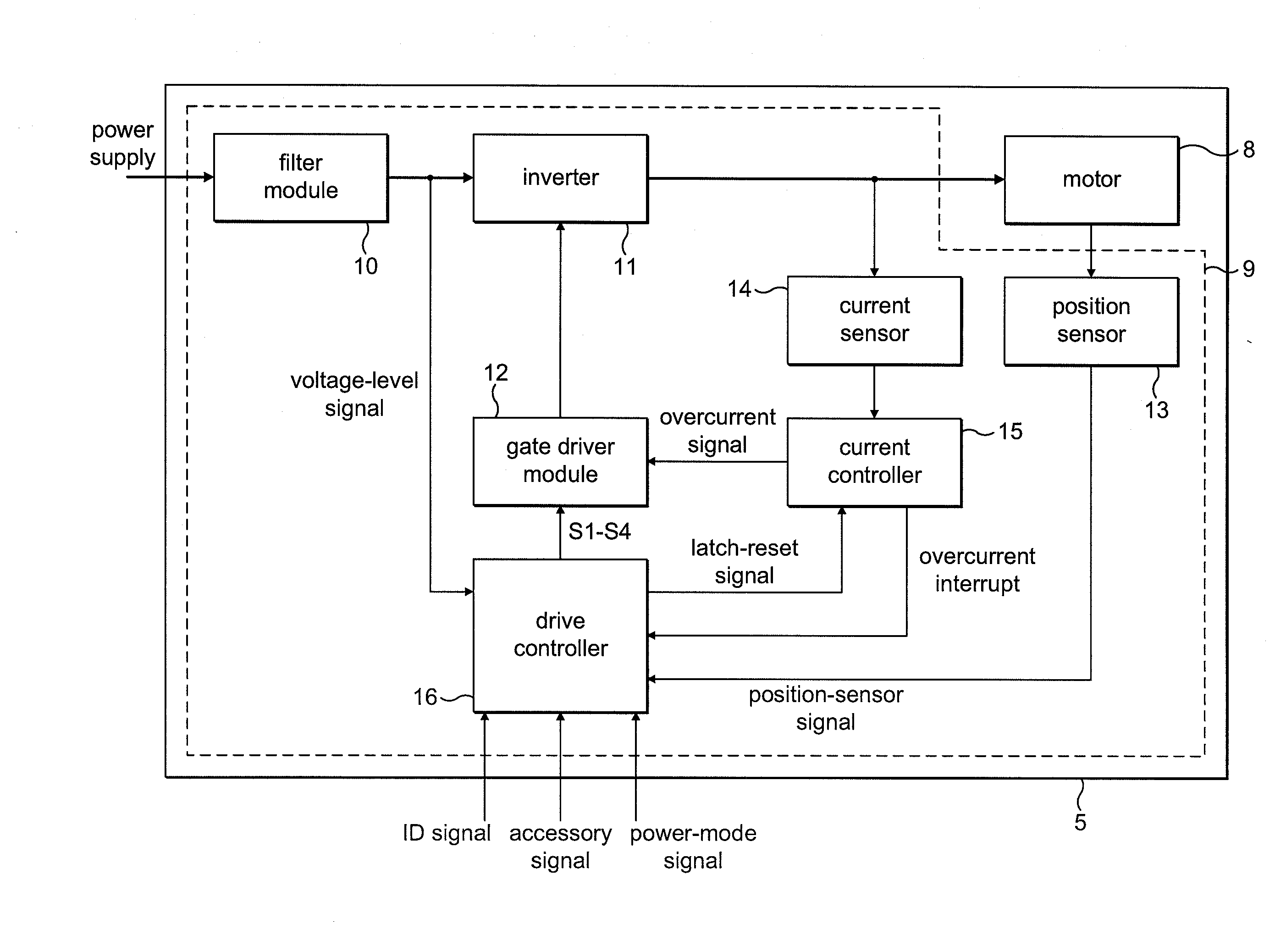
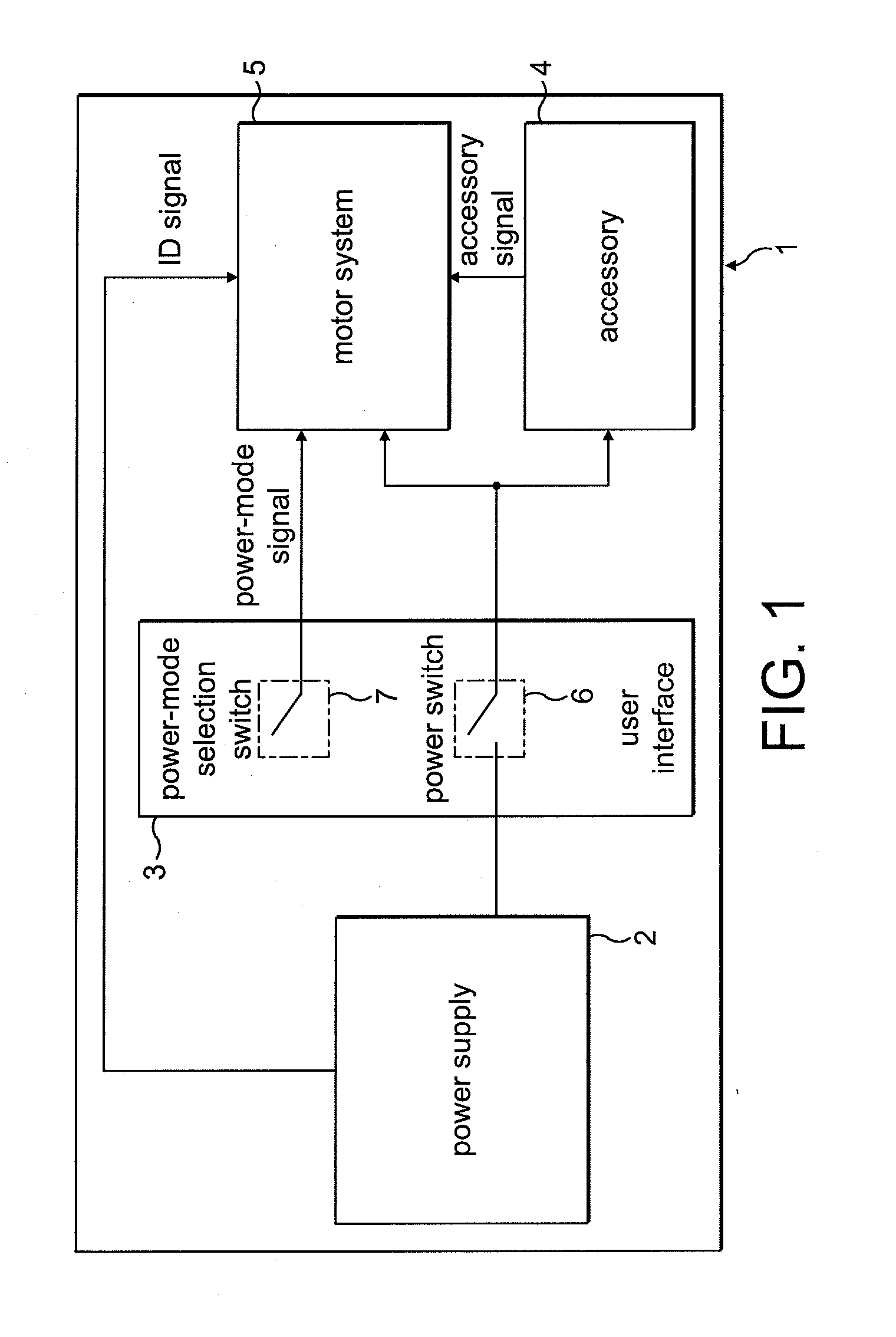
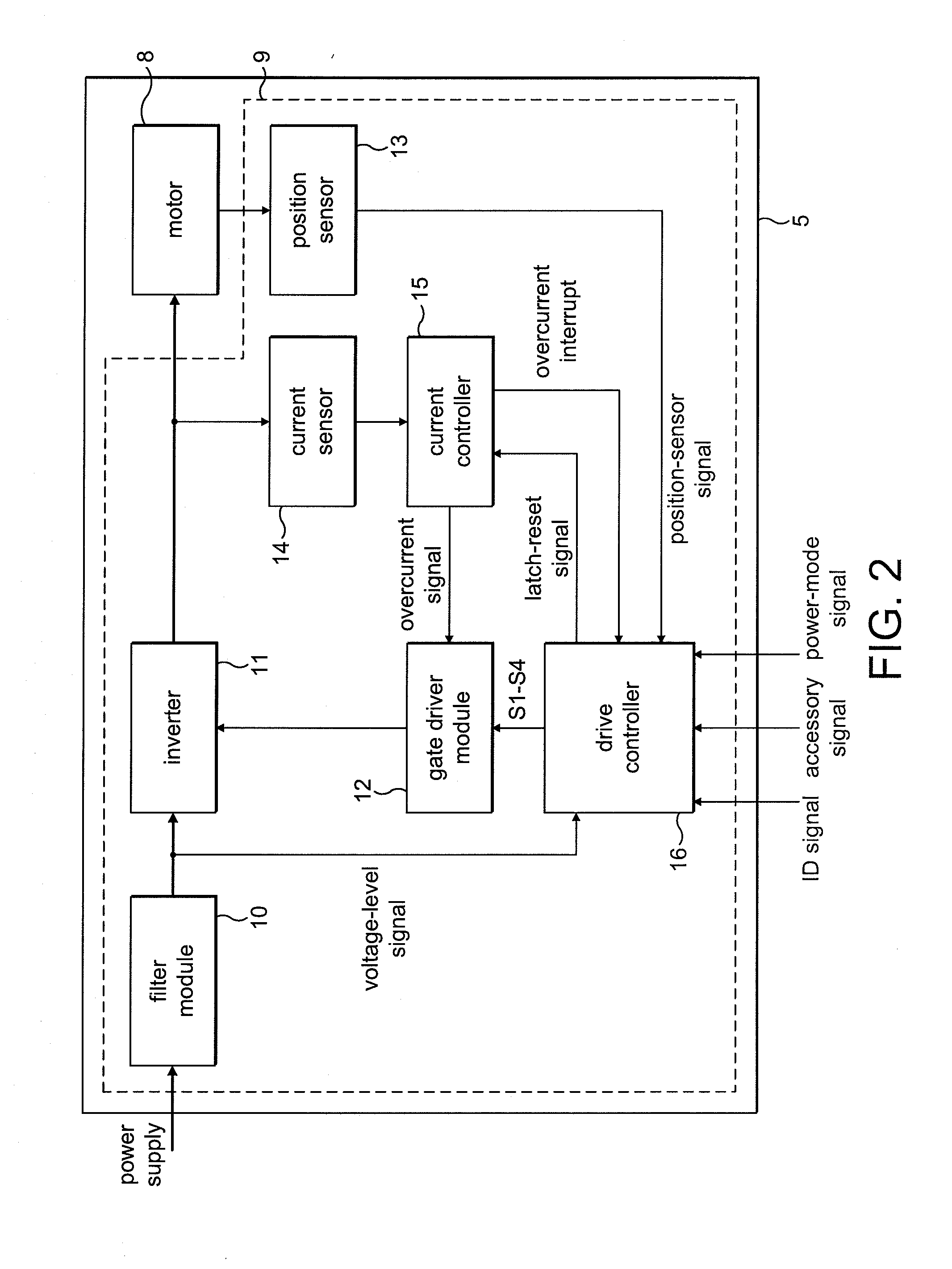
[0031]The product 1 of FIG. 1 comprises a power supply 2, a user interface 3, an accessory 4, and a motor system 5.

[0032]The power supply 2 comprises a battery pack that supplies a DC voltage to both the accessory 4 and the motor system 5. The power supply 2 is removable from the product 1 such that the product 1 may be used with different battery packs. For the purposes of the present description, the power supply 2 is either a 4-cell battery pack providing a 16.4 V DC supply or 6-cell battery pack providing a 24.6 V DC supply. In addition to providing a supply voltage, the power supply outputs an identification signal that is unique to the type of battery pack. The ID signal takes the form of a square-wave signal having a frequency that varies according to the type of battery pack. In the present example, the 4-cell battery pack outputs an ID signal having a frequency of 25 Hz (20 ms pulse length), while the 6-cell battery pack outputs an ID signal having a frequency of 50 Hz (10 ...


PUM


Abstract

A control system for an electric machine, the control system including a position sensor and a drive controller. The drive controller generates one or more control signals for exciting a winding of the electric machine in response to edges of a signal output by the position sensor. The times at which the control signals are generated by the drive controller are corrected by a position-sensor offset that is fixed over an operating speed range of the electric machine.

Description

REFERENCE TO RELATED APPLICATIONS[0001]This application claims the priority of United Kingdom Application No. 0905888.4, filed Apr. 4, 2009, the entire contents of which are incorporated herein by reference.FIELD OF THE INVENTION[0002]The present invention relates to a control system for an electric machine.BACKGROUND OF THE INVENTION[0003]The output power of, an electric machine is critically dependant on accurate synchronisation of phase excitation and rotor position. Accordingly, the electric machine typically includes a position sensor for determining the position of the rotor.[0004]Following assembly of the electric machine, there is a tolerance in the alignment of the position sensor relative to the rotor. This tolerance in alignment results in a phase difference between the detected position and the actual position of the rotor. As a result, phase excitation and rotor position are not perfectly synchronised and thus the power and efficiency of the motor are compromised.[0005]...

Claims


Application Information

Patent Timeline
Patent Type & Authority Applications(United States)
IPC IPC(8): H02P23/12
CPCA47L5/26A47L9/2831A47L9/2847A47L9/2884H02P29/026H02P6/008H02P6/085H02P6/145A47L9/2889H02P6/153H02P6/26H02K29/08H02P6/16H02P6/17
Inventor CELIK, TUNCAY
Owner DYSON TECH LTD
Why Eureka
Try Eureka