Device for connecting transverse beam at triangular position of vertebral lamina

Inactive Publication Date: 2012-11-08
YEH CHUNG CHUN
View PDF5 Cites 14 Cited by
  • Summary
  • Abstract
  • Description
  • Claims
  • Application Information

AI Technical Summary

Benefits of technology

[0009]The objective of the present invention is to provide a device for mounting a transverse beam at a triangular position of a vertebral lamina, which strengthens patients with unstable spinal structure the stability of the vertebral body via the device of the present invention.

Problems solved by technology

However, even the conventional methods have been adopted for connecting and fixing a posterior spine for a long time, yet they still have drawbacks and may not be suitable for some situations.
For instance, the pedicle screw fixation system 1 is not applicable for certain spinal diseases such as the collapse or osteoporosis of vertebral bodies, because the screw 13 section of a pedicle may not be able to be fixed onto the vertebral bodies effectively, and the pedicle screw fixation system 1 on the spine may become loose after a period of time, which may pose a threat to the patient and a surgery may be required to adjust the loosened screws.
For example, any interspinous process fixation device cannot be connected directly and effectively to other fixation system(s).
Therefore, the aforementioned conventional pedicle screw fixation system and related surgical methods still have their drawbacks and inapplicability, and thus require further reviews, improvements and it is necessary to develop a device for connecting a transverse beam at a triangular position of a vertebral lamina to overcome the problems.

Method used


Image

  • Device for connecting transverse beam at triangular position of vertebral lamina
  • Device for connecting transverse beam at triangular position of vertebral lamina
  • Device for connecting transverse beam at triangular position of vertebral lamina

Examples


Embodiment Construction

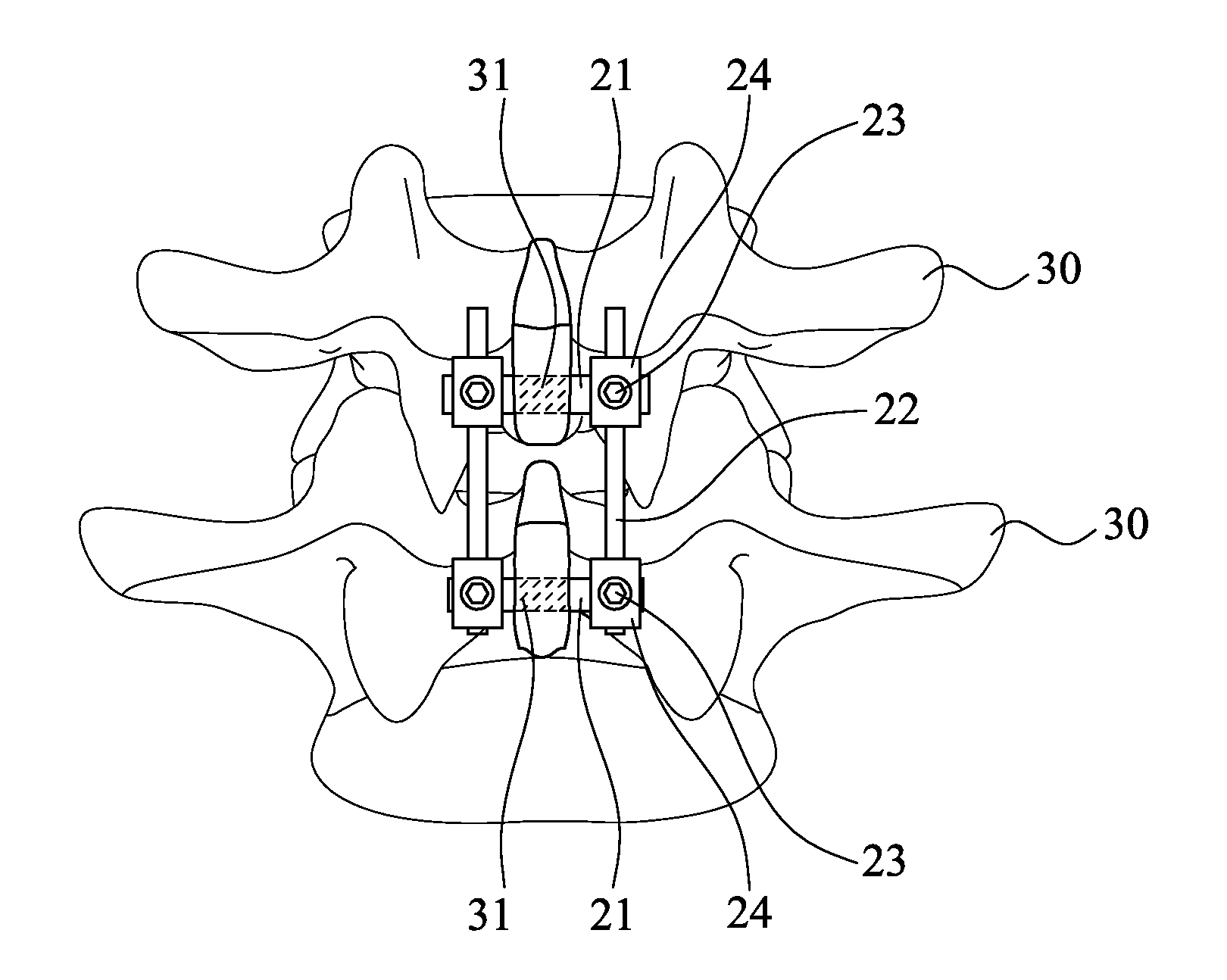
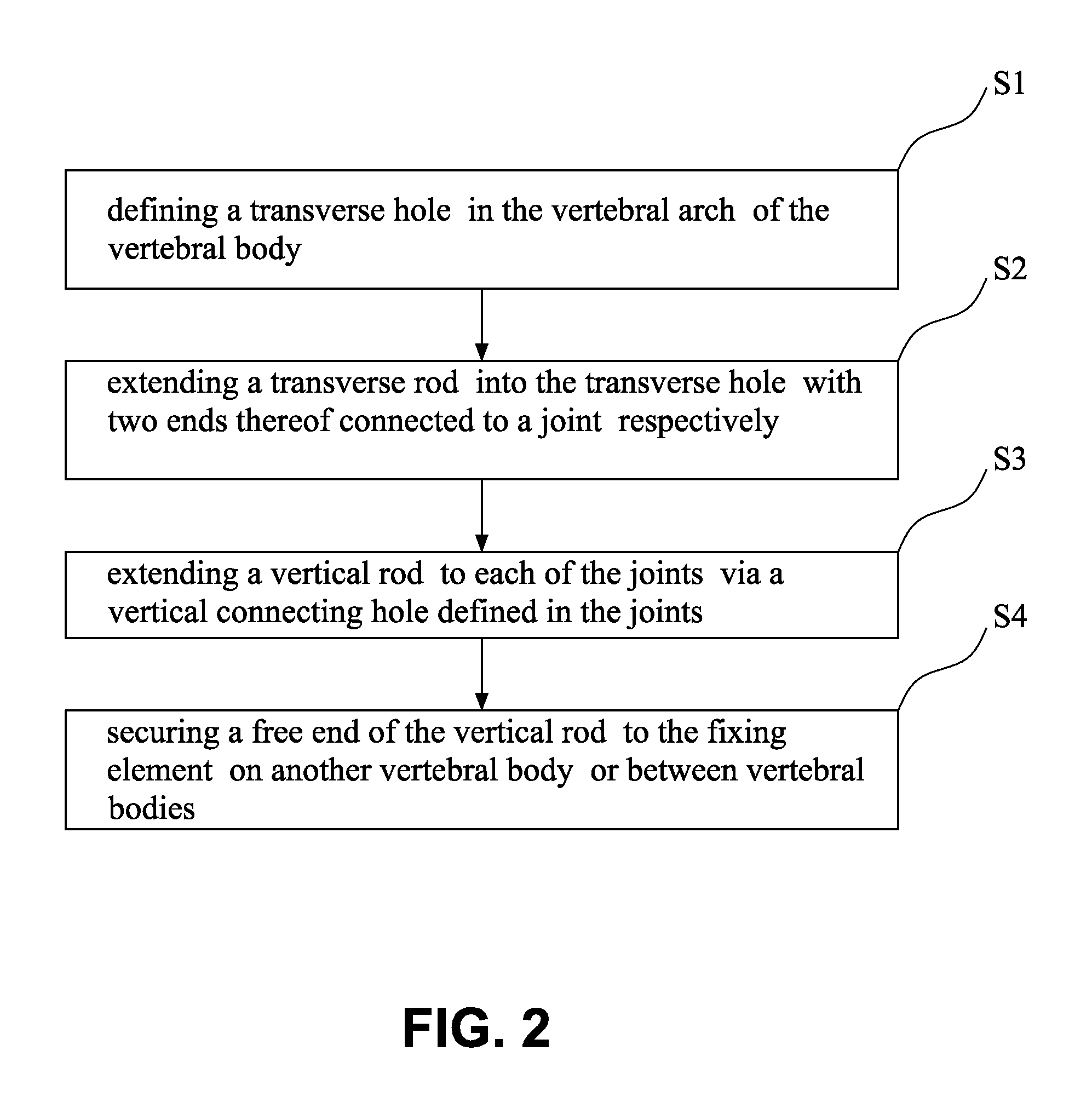
[0022]With reference to FIGS. 2 to 6, the device for connecting a transverse beam at a triangular position of a vertebral lamina constructed in accordance with the present invention includes at least one fixing element 2, which is used for fixing a vertebra. The connecting steps of the present invention are as the following: (shown as FIG. 2)

[0023]Step S1, defining a transverse hole 31 in the vertebral arch 302 of the vertebral body 30, wherein the transverse hole 31 is defined in an area between the bottom vertex of the lamina of vertebral arch and the top vertex of the spinous process;

[0024]Step S2, extending a transverse rod 21 into the transverse hole 31 with two ends thereof connected to a joint 24 respectively;

[0025]Step S3, extending a vertical rod 22 to each of the joints 24 via a vertical connecting hole defined in the joints; and

[0026]Step S4, securing a free end of the vertical rod 22 to the fixing element 2 on another vertebral body 30 or between vertebral bodies (not sh...


PUM


Abstract

A fixing device for securing vertebral lamina includes a transverse rod, a vertical rod having a length longer than that of the transverse rod and a joint having a vertical hole to securely receive therein a portion of the vertical rod and a cutout communicating with the vertical rod to receive therein a portion of the transverse rod.

Description

CROSS-REFERENCE TO RELATED APPLICATIONS[0001]This application is a continuation-in-part of a co-pending non-provisional application, titled “Method of Connecting Transverse Beam at Triangular Position of Vertebral Lamina”, with Ser. No. 12 / 750,942 and filed on Mar. 31, 2010 by the same applicant of this instant application. The description thereof is incorporated herein by reference.BACKGROUND OF THE INVENTION[0002]1. Field of the Invention[0003]The present invention relates to a device for connecting a transverse beam at a triangular position of a vertebral lamina, and more particularly to a device used for fixing a transverse beam at a triangular intersection position between a spinous process and a lamina of vertebral arch of a human spine for connecting and fixing a posterior spine.[0004]2. Description of Related Art[0005]Most conventional devices for connecting and fixing the posterior spine adopt a pedicle screw fixation system 1 (as shown in FIGS. 1a and 1b) having a pluralit...

Claims


Application Information

Patent Timeline
IPC IPC(8): A61B17/70
CPCA61B17/7062A61B17/7068A61B17/7067
Inventor YEH, CHUNG-CHUN
Owner YEH CHUNG CHUN
Why Eureka
Try Eureka