Grommet

a technology of grommet and spherical plate, which is applied in the direction of multi-purpose tools, electric/fluid circuits, vehicle components, etc., can solve the problems of poor waterproofing effect, poor adhesion between the lip and and the proportion of the lip in direct contact with the body panel through-hole is likely to deform, etc., to achieve good waterproofing

Inactive Publication Date: 2012-11-15
SUMITOMO WIRING SYST LTD
View PDF4 Cites 3 Cited by
  • Summary
  • Abstract
  • Description
  • Claims
  • Application Information

AI Technical Summary

Benefits of technology

[0010]In view of the above issues, the present application provides a grommet able to inhibit deformation of a waterproofing portion, the waterproofing achieved by contact with a panel, such as on a vehicle body, as well as to achieve good waterproofing.

Problems solved by technology

Thus, when the path of the wire harness is skewed, due to a bend developing in the wire harness, for example, while the grommet is attached to the through-hole, portions of the lip in direct contact with the body panel through-hole are likely to deform.
Accordingly, there is a risk that adhesion worsens between the lip or the flange and the peripheral edge of the body panel through-hole and that the seal will deteriorate.
Accordingly, there is a risk that this force will deform the portions of the grommet touching the panel and deteriorate the seal.

Method used


Image

  • Grommet
  • Grommet
  • Grommet

Examples


first embodiment

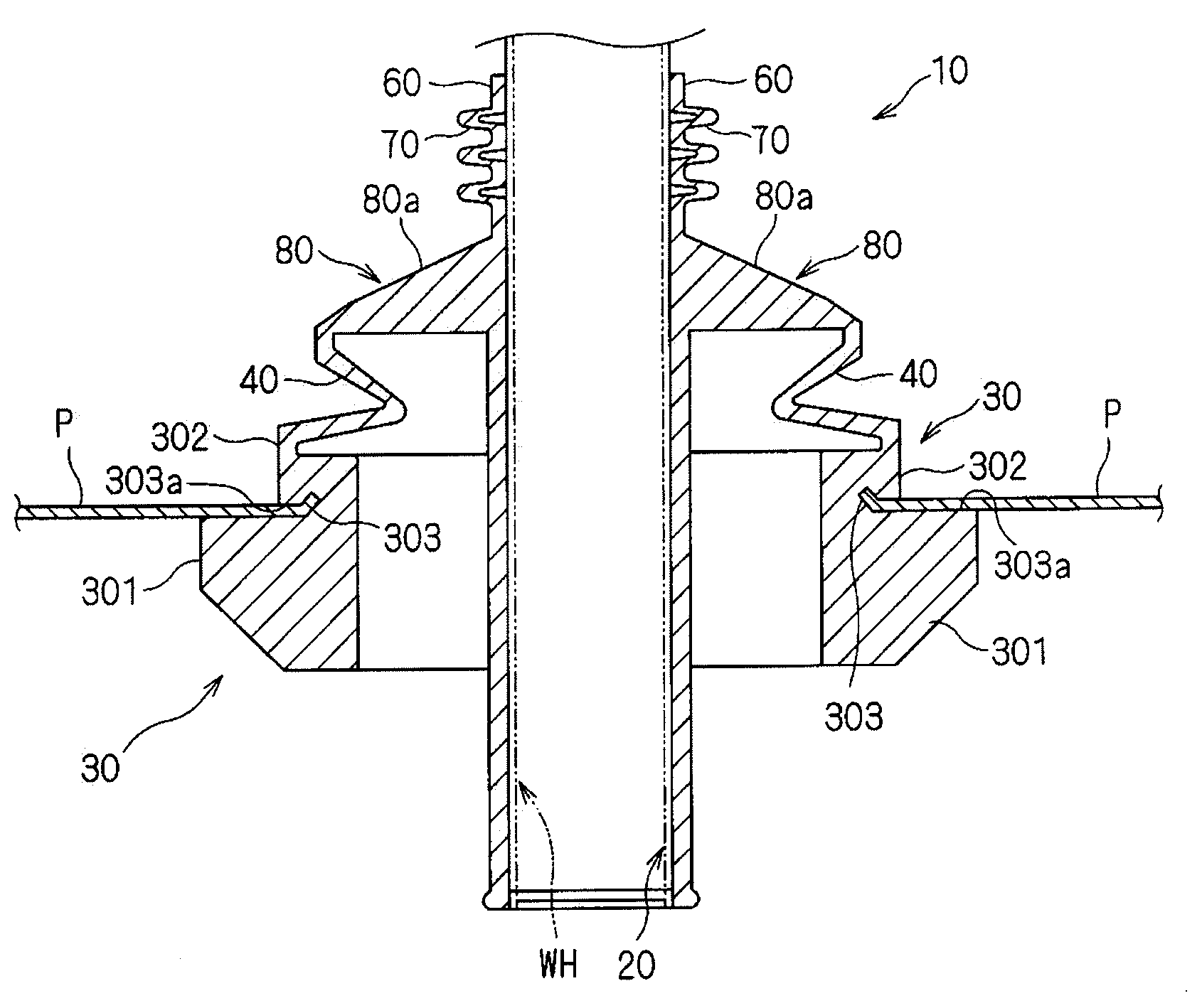
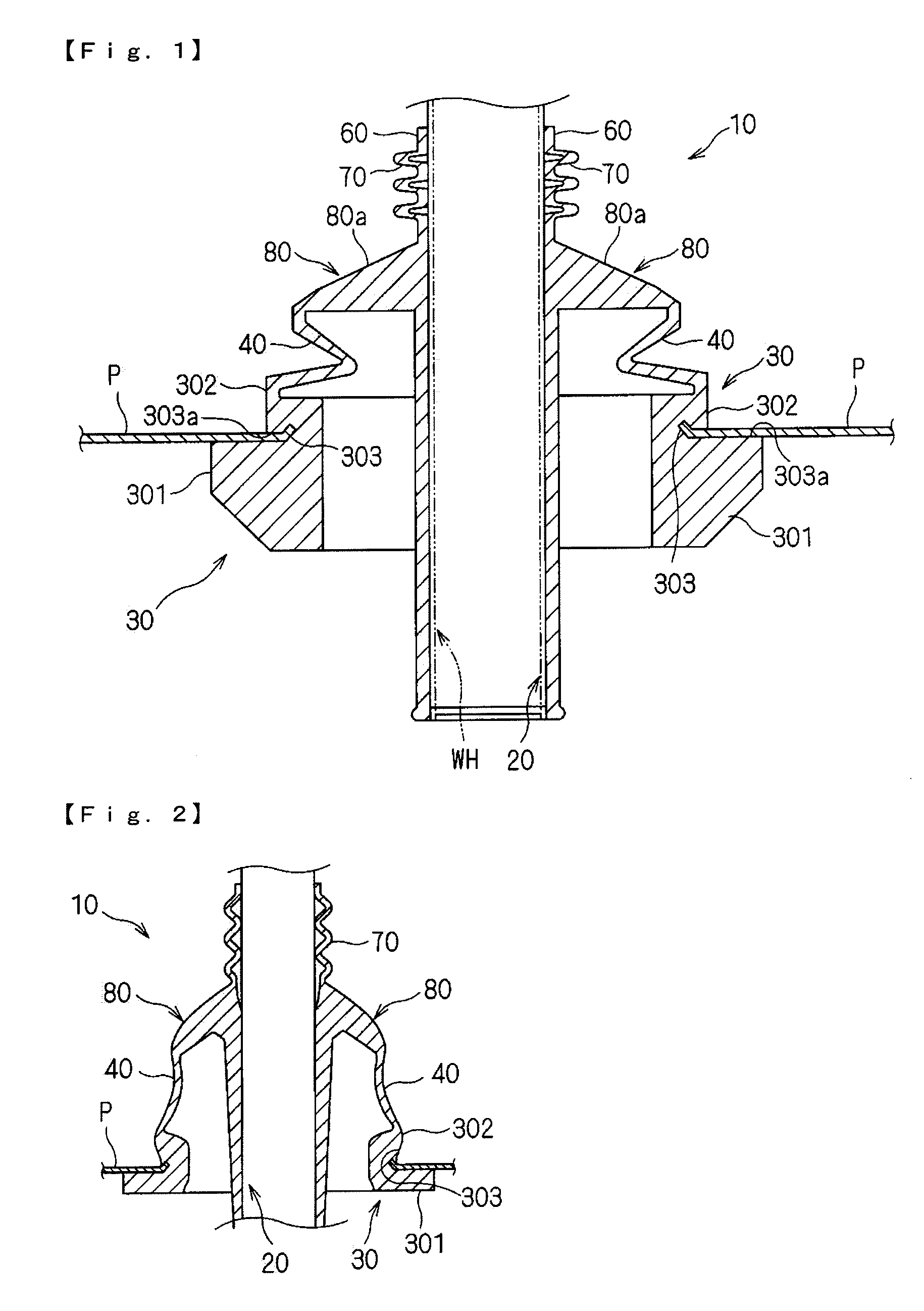
[0028]FIG. 1 is a cross-sectional view of a grommet 10 according to a first embodiment of the present invention.

[0029]The grommet 10 has a resin structure integrally molded from any suitable elastic material, such as synthetic rubber. The grommet 10 is inserted into and fixated in a through-hole formed in a vehicle body panel P of a vehicle such as an automobile, such that the grommet 10 is mounted over a wire harness WH.

[0030]In the interior of the grommet 10, a wire passage 20 is provided as a portion through which the wire harness WH is inserted. The wire passage 20 according to the present embodiment has a shape allowing housing of the wire harness WH which is positioned so as to be straight. Each portion of the grommet 10 is provided contiguously around the wire passage 20.

[0031]A tape-wound portion 60 at which tape is wound around the wire housing WH and the grommet 10 is provided around one end of the wire passage 20 disposed on the outer side of a vehicle body panel P. The w...

second embodiment

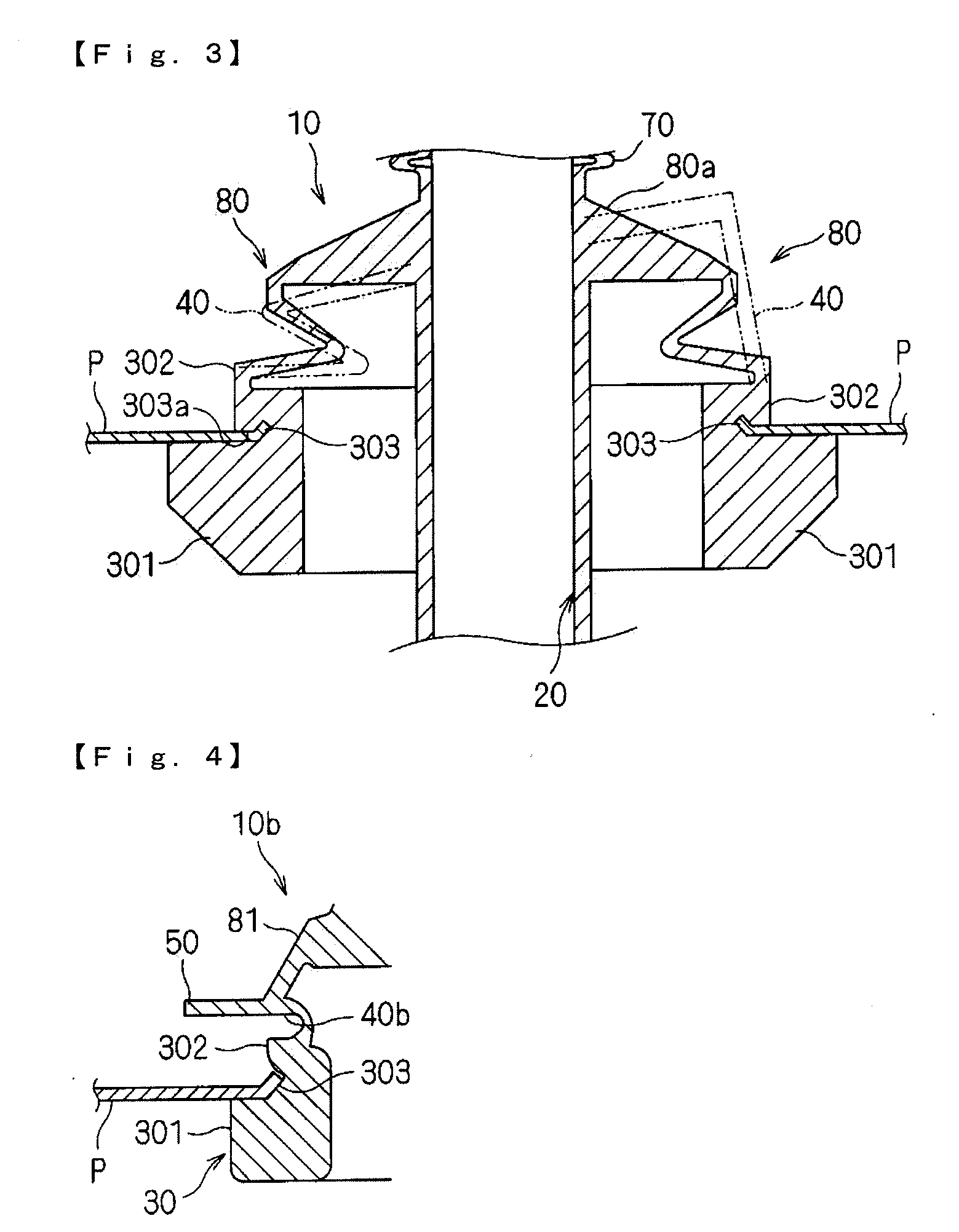
[0054]The grommet 10 of the present invention is not limited to the first embodiment described above. It may also have other forms. FIG. 4 shows a partial cross-sectional view of a grommet 10b according to a second embodiment. The same reference numerals are assigned to portions that are the same as the grommet 10 according to the first embodiment described above, and the explanation thereof is omitted.

[0055]A connector 81 according to the present embodiment has an annular shape having a curved portion recessed to an inner periphery, the recessed portion following the circumferential direction. In the present embodiment, this portion is called a stretching portion 40b. The stretching portion 40b curves such that it recesses to an inner periphery, bending in a U-shape to the inner periphery on a longitudinal section. That is, the stretching portion 40b bends such that the width of the opening edge of the recessed portion either increases or decreases.

[0056]The grommet 10b according t...


PUM

PropertyMeasurementUnit
elasticaaaaaaaaaa
annular shapeaaaaaaaaaa
diameteraaaaaaaaaa

Abstract

A grommet includes a wire passage supporting a wire harness, a pinch-grip, and a connector. The pinch-grip is fixable to a vehicle body panel by pinching a peripheral edge of the panel surrounding a through-hole. The connector has an annular shape having a curved portion recessed to an inner periphery, the recessed portion extending in a peripheral direction. One end of the connector is joined to the wire passage and the other end is joined to the pinch-grip.

Description

CROSS-REFERENCE TO RELATED APPLICATIONS[0001]The present application claims priority under 35 U.S.C. §119 of Japanese Application No. 2011-108254, filed on May 13, 2011, the disclosure of which is expressly incorporated by reference herein in its entirety.BACKGROUND OF THE INVENTION[0002]1. Field of the Invention[0003]The present invention relates to a grommet mounted in a through-hole formed on a panel, such as on a vehicle body, such that the grommet is mounted over a wire harness.[0004]2. Description of Related Art[0005]Technology is known for a grommet being mounted over a wire harness, such as that described hereafter.[0006]For example, Japanese Patent Laid-open Publication No. 2008-234904 discloses a grommet including a circular connector around the outer periphery of a central axis in which a wire harness has been inserted. A lip is stretchably joined to the circular connector in an axis-central direction and a flange is joined to the lip.[0007]Japanese Patent Laid-open Publi...

Claims


Application Information

Patent Timeline
Patent Type & Authority Applications(United States)
IPC IPC(8): H01B17/26
CPCB60R16/0222Y10T16/063Y10T16/05H02G3/22
Inventor SHITAMICHI, MASARU
Owner SUMITOMO WIRING SYST LTD
Why Eureka
Try Eureka