
Device for directional drilling

a directional drilling and string section technology, applied in the direction of directional drilling, drilling accessories, drilling machines and methods, etc., can solve the problems of not being able to achieve a good adjustment in the opposite direction, requiring continuous rotation of the bearings of the drill bit shaft, and requiring a great deal of force in order to bend the drill string

Active Publication Date: 2012-11-15
NABORS LUX 2 SARL
View PDF12 Cites 26 Cited by
  • Summary
  • Abstract
  • Description
  • Claims
  • Application Information

AI Technical Summary

Benefits of technology

[0011]The object of the present invention is thus to provide a new and efficient device for controlling angle and deflection in directional drilling when using a “push-the-bit” device, which is arranged such that direction and deflection can be adjusted continuously, even whilst the drilling string rotates.
[0016]With this device for directional drilling there is no need for external moving parts, with the attendant possibilities of leakage in seals. This solution also gives a greater contact face against the formation, which may be advantageous when drilling in soft formations. Furthermore, since the new solution has the steering integrated in a stabiliser, the drill bit vibrations will be smaller, with the result that a better quality borehole is obtained.

Problems solved by technology

The disadvantage of this solution is that it requires continuous rotation of the bearings for the drill bit shaft at the same speed as, and in the opposite direction to, the drill string.
The drawback of this solution is that it requires a great deal of force in order to bend the drill string, in addition to the possibility of problems of fatigue arising due to rotation whilst the shaft is bent.
The three steering bodies, which are individually movable, may, however, be subject to problems during operation, for example, leakages at the seals around the movable steering bodies.
With this solution it is not possible to achieve a good adjustment in the opposite direction of the pregnant or weighted side 20.
This means that the tool taught in this document is rather inflexible in use.
However, this apparatus is constructed such that it is not possible to adjust direction and deviation separately; if direction is adjusted, deflection must also be adjusted or vice versa.

Method used


Image

  • Device for directional drilling
  • Device for directional drilling
  • Device for directional drilling

Examples


Embodiment Construction

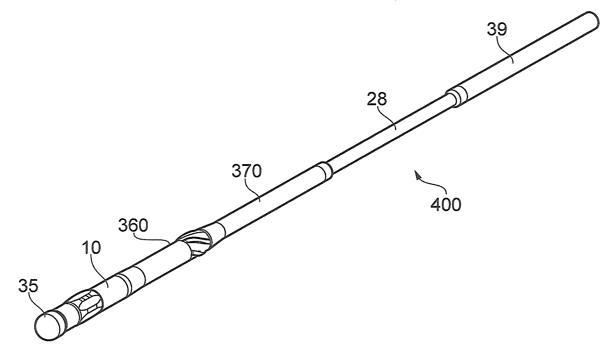
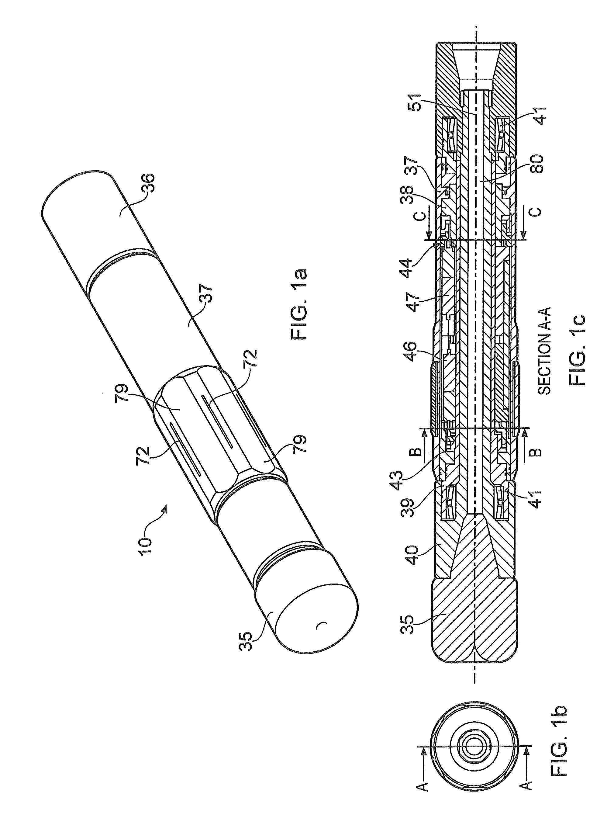
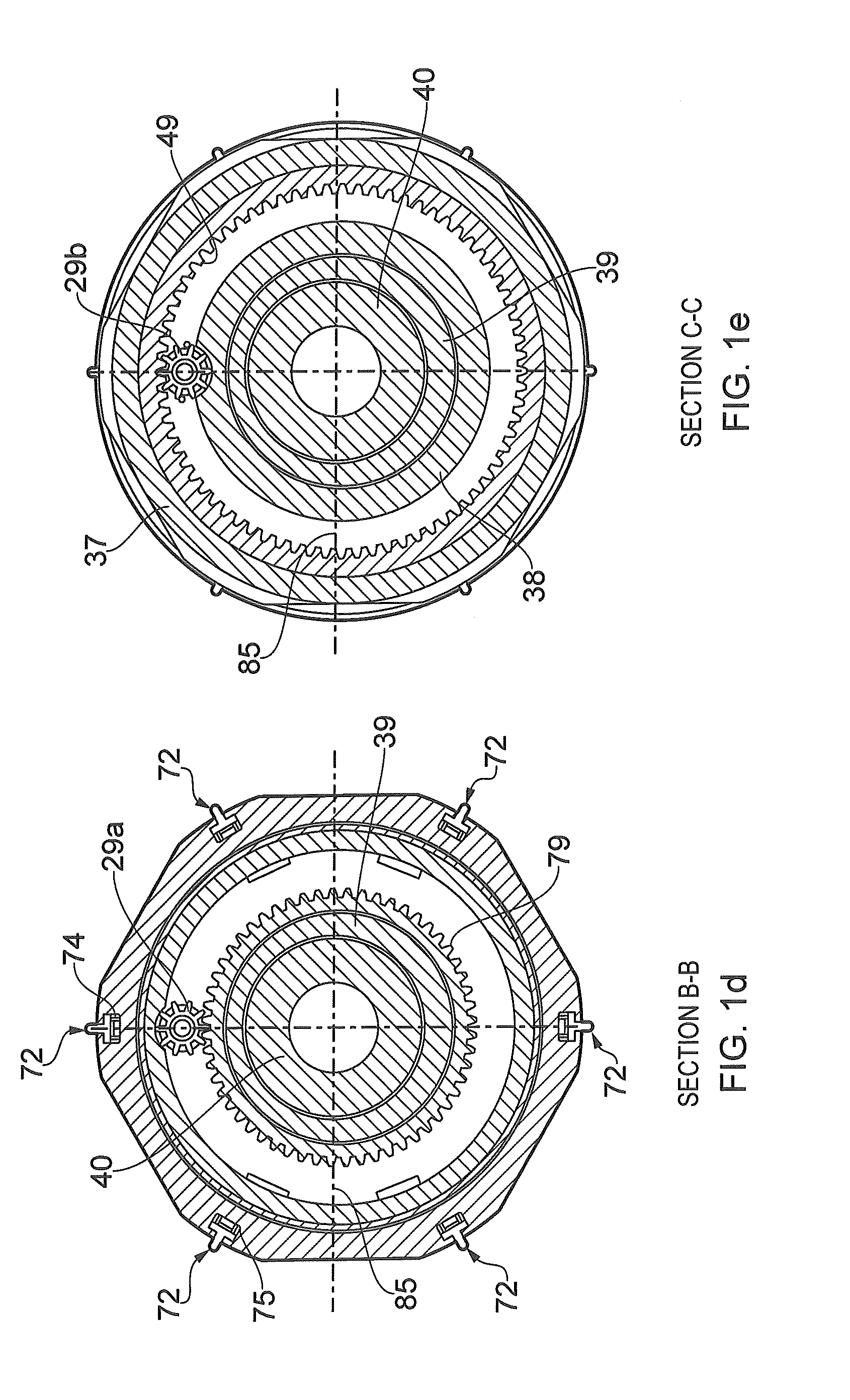
[0039]FIG. 1a shows a drill string having a drill string section 10 comprising a drill bit 35, a drill string section 10 with a rotational mechanism encased by an outer casing 37 in a neutral position, i.e., that the drill string section 10 is not set with any deviation from the centre axis of the drill string (drilling “straight ahead”). The drill string section 10 rests against the surroundings to give counterforce during directional drilling and to stabilise the drill bit, and is equipped with return channels 79 in the surface to allow for return flow of drilling fluids. The outer casing 37 of the drill string section 10 is also provided with one or more anti-rotational mechanisms 72 to prevent or at least reduce rotation of the outer casing in relation to the surroundings. It is not essential that the outer casing should be equipped with anti-rotational mechanisms 72 in order for it to have sufficient grip in relation to the surroundings, but their use may be desirable in some c...


PUM


Abstract

A drill string section for directional drilling includes an outer casing which encases an adjustment mechanism for adjusting drilling direction and angular deflection during drilling. The adjustment mechanism has an outer shaft that is rotatably arranged relative to the outer casing and is configured with an axial eccentric first bore having a first bore axis that is parallel to the centre axis. The adjustment mechanism further includes an inner shaft that is rotatably arranged in the first bore and is configured with an axial, eccentric second bore for passage of a drive shaft for a drill bit

Description

FIELD OF THE INVENTION[0001]The present invention relates to a drill string section for use in directional drilling.BACKGROUND[0002]When drilling oil and / or gas wells, it will often be necessary to guide the drilling tool in a desired direction out of the tool's drilling direction. This is the case, for example, in connection with directional wells which may have a substantial deviation from a vertical direction.[0003]During drilling it is common to use a drill bit connected to a drill string, which drill string and drill bit are rotated about their longitudinal, axial axes by a drive unit which may be located at the surface.[0004]Directional control of the drilling tool can be affected by applying to the drill bit a radial force which is designed to drive the bit to drill at a certain deviation in a desired direction in relation to the centre axis of the bit. The drilling tool may also have provided therein a gyroscope, one or more accelerometers or one or more magnetometers which ...

Claims


Application Information

Patent Timeline
IPC IPC(8): E21B7/08
CPCE21B7/06E21B7/064E21B7/062
Inventor KVALVIK, TORE
Owner NABORS LUX 2 SARL
Learn More