Transporting device and image forming apparatus using the same

Active Publication Date: 2012-11-15
KONICA MINOLTA BUSINESS TECH INC
View PDF7 Cites 24 Cited by
  • Summary
  • Abstract
  • Description
  • Claims
  • Application Information

AI Technical Summary

Benefits of technology

[0025]It is to be noted that even if a length of the sheet of paper along the second direction exceeds the previously set length of the reference sheet of paper, when the sheet of paper is transparent such as a sheet of paper for overhead projector (OHP), it may be difficult to detect the sheet of paper. In such a case, the control unit may perform the first positional deflection correction control. Thus, by classifying the positional deflection correction controls of the sheet of paper based on the length of the sheet of paper along the second direction, it is possible to perform the positional deflection correction control of the sheet of paper in re

Problems solved by technology

Accordingly, the past transporting device and the past image forming apparatus have increased costs therefor.
Because a plurality of the deflection detection sensors and co

Method used


Image

  • Transporting device and image forming apparatus using the same
  • Transporting device and image forming apparatus using the same
  • Transporting device and image forming apparatus using the same

Examples


Example

First Embodiment

Configuration Example of Image Forming Apparatus

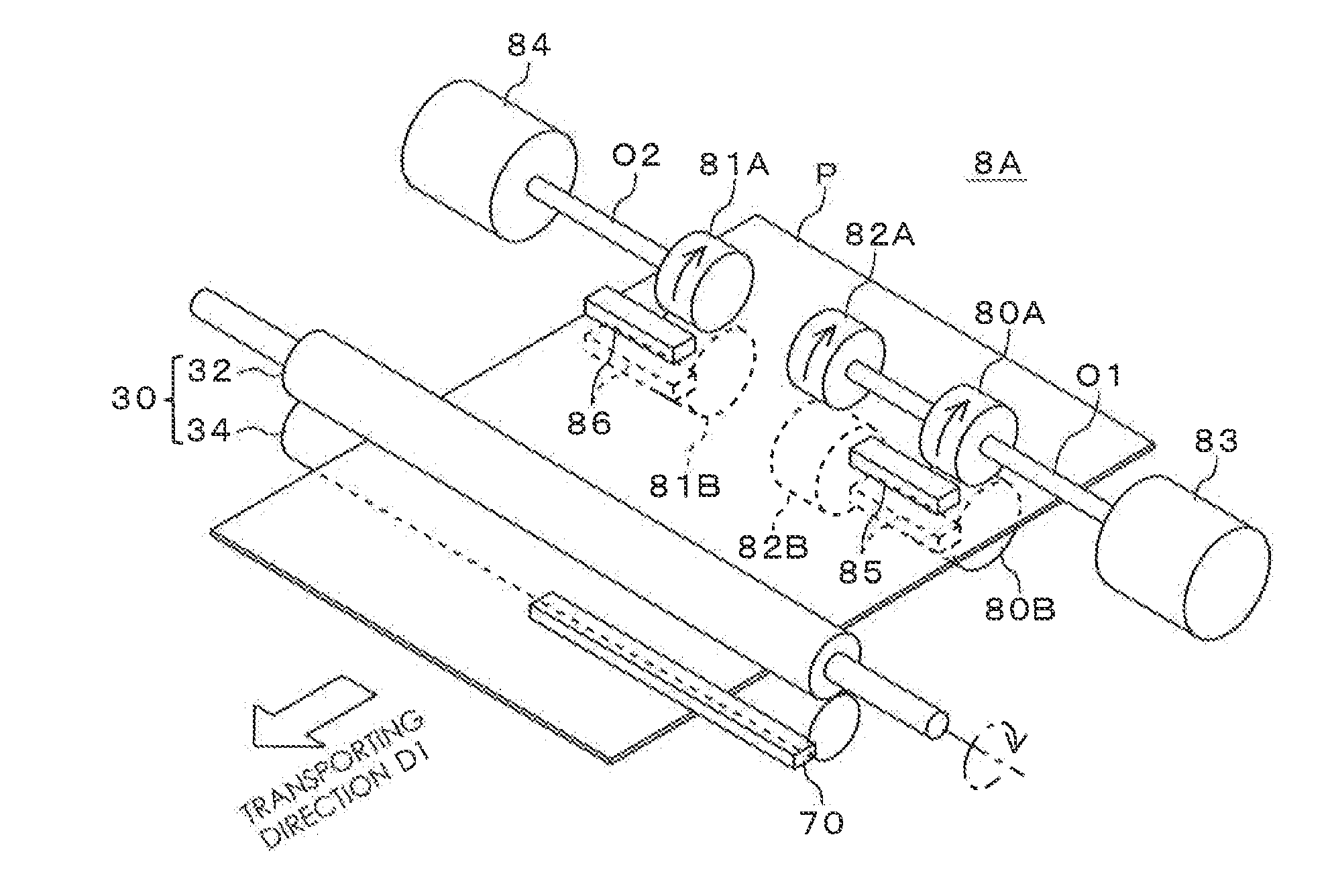
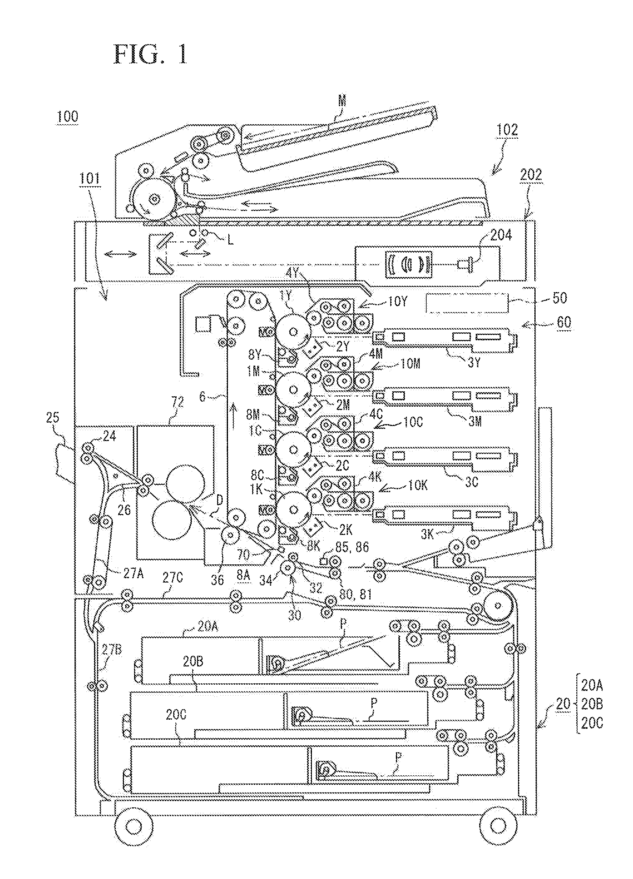
[0039]FIG. 1 schematically shows a configuration example of the image forming apparatus 100 according to a first embodiment of this invention. The image forming apparatus 100 according to a first embodiment of this invention switches between a first positional deflection correction control of the sheet of paper and a second positional deflection correction control of the sheet of paper based on a length of a sheet of paper P on which an image is formed along a direction (herein after, also referred to as “width direction”) which is orthogonal to a transporting direction D1 of the sheet of paper P, specifically based on a width W1 of a reference sheet of paper which is previously set. The width W1 of a reference sheet of paper is a reference width when switching between the first positional deflection correction control of the sheet of paper and the second positional deflection correction control of the sheet of paper. T...

Example

Second Embodiment

[0091]Although the first positional deflection correction has been performed using the center roller 82 in the first embodiment, the second embodiment is different from the first embodiment in that the first positional deflection correction is performed using the steering rollers 80, 81. It is to be noted that other components of the image forming apparatus 100 in this embodiment are identical to those of the first embodiment so that the identical components are indicated by the same reference numbers, a detailed explanation of which will be omitted.

[0092]FIG. 12A shows a side view of a transporting device 8B according to the second embodiment, seen from a direction which is orthogonal to the transporting direction D1 of the sheet of paper P. FIG. 12B shows a plan view thereof. FIG. 12C shows a front view thereof, seen from a direction which is parallel to the transporting direction D1 of the sheet of paper P. As shown in FIGS. 12A through 12C, the transporting devi...


PUM


Abstract

A transporting device includes steering rollers, a center roller which is disposed between the steering rollers and deflection-detecting sensors that are positioned downstream from the steering rollers. When a sheet of paper has a width which is narrower than a width of a reference sheet of paper, the positional deflection of the sheet of paper is corrected by transporting the sheet of paper to a shift roller with the sheet of paper being nipped by the center roller and thrusting a forward end of the sheet of paper against a shift roller. When a sheet of paper has a width which exceeds the width of the reference sheet of paper, the positional deflection of the sheet of paper is corrected by rotating the steering rollers separately based on a detected result of the sensors with the sheet of paper being nipped by the steering rollers.

Description

CROSS REFERENCES TO RELATED APPLICATIONS[0001]The present invention contains subject matter related to Japanese Patent Application JP 2011-106290 filed in the Japanese Parent Office on May 11, 2011, the entire contents of which being incorporated herein by reference.BACKGROUND OF THE INVENTION[0002]1. Field of the Invention[0003]The present invention relates to a transporting device that transports a sheet of paper and is equipped with a function of a positional deflection correction for a sheet of transporting paper, and an image forming apparatus using the same.[0004]2. Description of Related Art[0005]An image forming apparatus equipped with multiple functions, which is simultaneously provided with various functions such as a printer, scanner, a copy machine and a facsimile, has been widely used in recent years. In such an image forming apparatus, a sheet of paper may be deflected to an offset position while the sheet of paper is transported because of mechanical factors or the li...

Claims


Application Information

Patent Timeline
IPC IPC(8): B65H7/06
CPCB65H7/06B65H9/002B65H2801/06B65H2701/1311B65H2553/82B65H2553/416B65H2513/53B65H2513/104B65H2511/514B65H2511/416B65H2511/414B65H2511/10B65H2404/144B65H9/006B65H2404/133B65H2220/01B65H2220/02B65H2220/03B65H2513/10B65H2513/52
Inventor UI, MAKOTO
Owner KONICA MINOLTA BUSINESS TECH INC
Why Eureka
Try Eureka