Stator and motor

a technology of inner rotor motor and rotor, which is applied in the direction of windings, dynamo-electric components, supports/encloses/casings, etc., can solve the problems of inability to hold the busbar unit, cumbersome continuous winding of a plurality of coils, and inferior workability, so as to prevent an increase in the size of the busbar unit, excellent versatility

Inactive Publication Date: 2012-11-15
NIPPON DENSAN CORP
View PDF6 Cites 71 Cited by
  • Summary
  • Abstract
  • Description
  • Claims
  • Application Information

AI Technical Summary

Benefits of technology

[0037]As described above, according to a preferred embodiment of the present invention, a stator and other elements of a motor are compa

Problems solved by technology

This presents an impediment to improving productivity.
However, continuous winding for a plurality of coils is cumbersome and has inferior workability.
In the case where an insulator is provided with a structure arranged to

Method used


Image

  • Stator and motor
  • Stator and motor
  • Stator and motor

Examples


first preferred embodiment

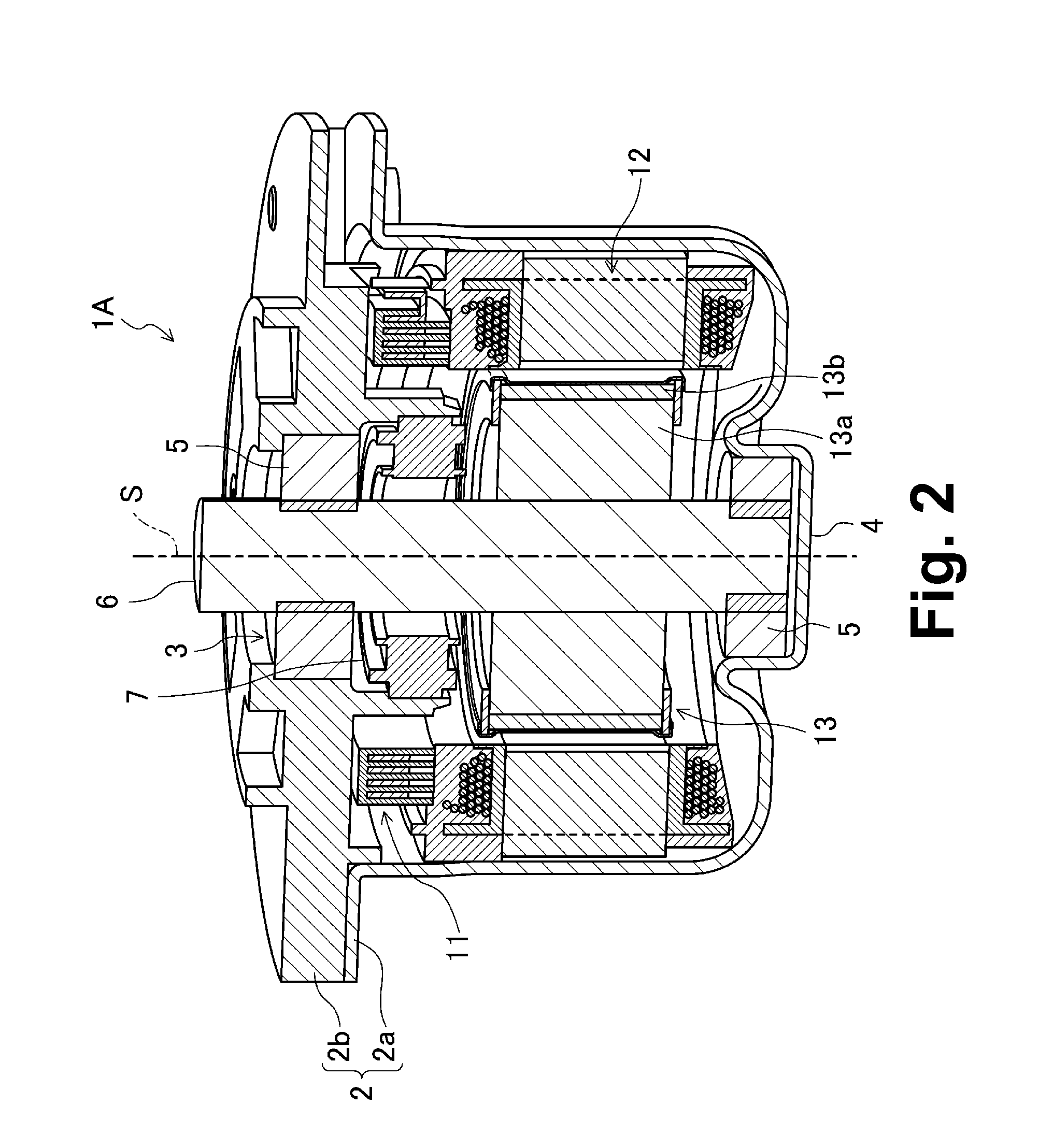
[0111]FIG. 2 illustrates a motor 1A according to a first preferred embodiment of the present invention. The motor 1A preferably is an inner-rotor brushless motor to be installed in a vehicle, and is preferably used to drive an electric power steering, for example. In particular, the motor 1A has an ability to switch between parallel connection and series-parallel connection, using the same stator. This is accomplished by attaching the passage-line busbars to the stator or removing the passage-line busbars from the stator when assembling the motor 1A.

[0112]Referring to FIG. 2, the motor 1A preferably includes a casing 2, a busbar unit 11, a stator 12, a rotor 13, a shaft 6, and so on. A center of each of the rotor 13, the stator 12, and the busbar unit 11 coincides with a center S (i.e., a rotation axis of the motor 1A) of the shaft 6.

[0113]The casing 2 preferably includes a receptacle 2a which includes a bottom and is substantially cylindrical, and a substantially disc-shaped lid 2b...

second preferred embodiment

[0172]FIG. 22 illustrates a motor 1 including a rotor 300 according to a preferred embodiment of the present invention. The motor 1 preferably is an inner-rotor brushless motor to be installed in a vehicle, and is used to drive an electric power steering, for example. As illustrated in FIG. 22, the motor 1 preferably includes a casing 2, a busbar unit 100, a stator 200, the rotor 300, a shaft 6, and so on.

[0173]The casing 2 preferably includes a receptacle 2a which has a bottom and is substantially cylindrical, and a substantially disc-shaped lid 2b. The lid 2b is preferably secured to a flange of the receptacle 2a. The flange of the receptacle 2a is preferably arranged to project radially outward around a circumference of an opening of the receptacle 2a. The stator 200 and so on are contained inside the receptacle 2a. A through hole 3 is preferably defined in a central portion of the lid 2b. A bearing portion 4 is preferably arranged on a bottom surface of the receptacle 2a to be o...


PUM


Abstract

A stator is compatible with a variety of wiring configurations and possesses excellent versatility, while also preventing an increase in the size of a busbar unit. The stator includes a plurality of stator segments joined together to assume a cylindrical shape. Each stator segment includes a core segment including a core back portion and a tooth portion; a coil including a pair of coil wire terminals; an insulating layer arranged between the coil and the tooth portion; and a resin layer arranged to have the entire coil except for the coil wire terminals embedded therein. The resin layers of the stator segments include a supporting structure defined therein to allow a wiring member to be connected with any of the coil wire terminals to be attached to and removed from the stator.

Description

BACKGROUND OF THE INVENTION[0001]1. Field of the Invention[0002]The present invention relates to an inner-rotor motor in which a stator includes a plurality of stator segments. In particular, the present invention relates to a wiring configuration of a stator.[0003]2. Description of the Related Art[0004]In general, motors have a variety of potential performance levels that are varied depending on the intended purposes of the motors. The number of poles of a rotor, the number of slots of the stator, the direction of the winding of coils, the arrangement of the coils, and so on are designed in accordance with a desired performance of the motor. Thus, there are a large variety of wiring configurations available for motors.[0005]For instance, referring to FIG. 1A, in an 8-pole 12-slot motor, a group of four coils connected in parallel may be provided for each of a U phase, a V phase, and a W phase. Moreover, the groups of coils for the respective phases may be connected in a Y configura...

Claims


Application Information

Patent Timeline
IPC IPC(8): H02K3/28H02K3/32
CPCH02K1/148H02K1/278H02K3/28H02K3/522H02K2203/12H02K15/03H02K15/095H02K15/12H02K2203/09H02K5/225
Inventor YOKOGAWA, TOMOYOSHINAKAGAWA, AIRIHIROKAWA, TSUYOSHI
Owner NIPPON DENSAN CORP
Why Eureka
Try Eureka