This helps you quickly interpret patents by identifying the three key elements:
Problems solved by technology
Method used
Benefits of technology
Benefits of technology
[0012]The present embodiment is specifically designed to safely remove the barrel bushing, recoil spring, and recoil spring plug, or spring plug, while providing the operator with much greater control over the energy store
Problems solved by technology
So, the weakness inherent in the long handled design is a failure to easily apply the required force in the proper direction.
Many practioners of the art would not place any hard object other than a properly sized cleaning rod inside the muzzle of the pistol, due to the possibility of damage to the rifling, which would prove immediately deleterious to accuracy.
Second, the elongate member revealed in Perry make the tool somewhat more cumbersome to transport than the current embodiment.
In summation, pri
Method used
Image
Click on the blue label to locate the original text in one second.
Reading with bidirectional positioning of images and text.
Examples
Embodiment Construction
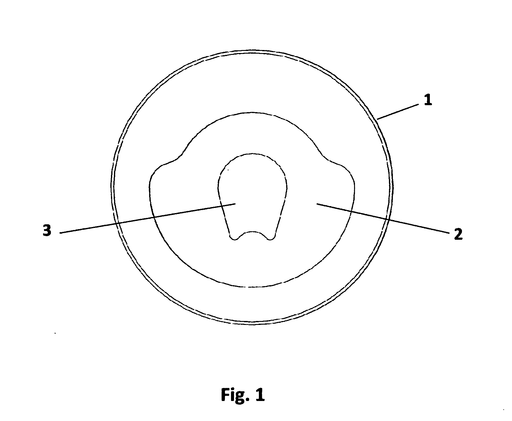
[0027]FIG. 1 shows a rear facing view of the generally annularlar body of the claimed embodiment (1) with recess in tool body. (2) and bushing opening (3). The tool body (1) is preferably comprised of any suitable and durable material, including, but not limited to, metal or plastic. The tool body (1) can be formed through various industrial processes such as investment casting, injection molding, wire electrode discharge machining or laser jet cutting.
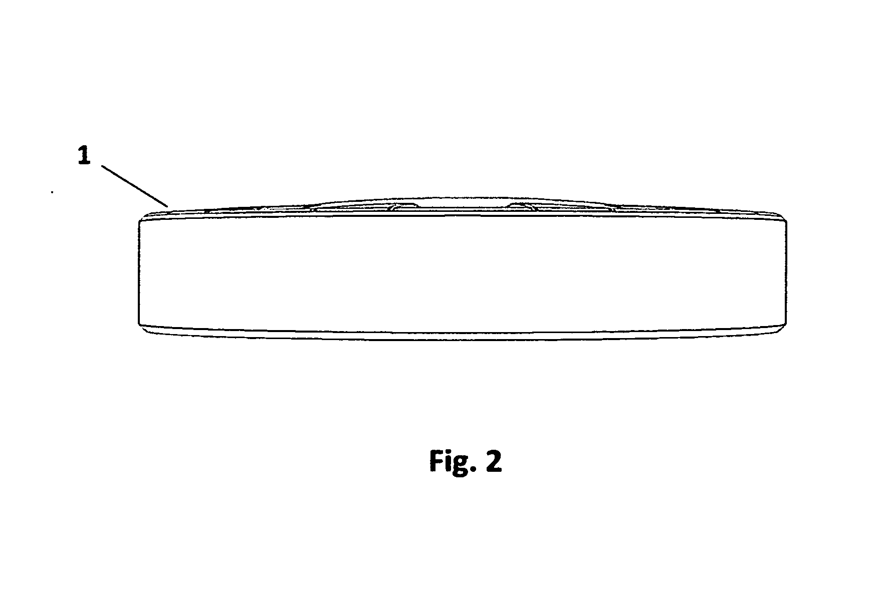
[0028]FIG. 2 shows a lateral sectioned view of the claimed embodiment. (1)
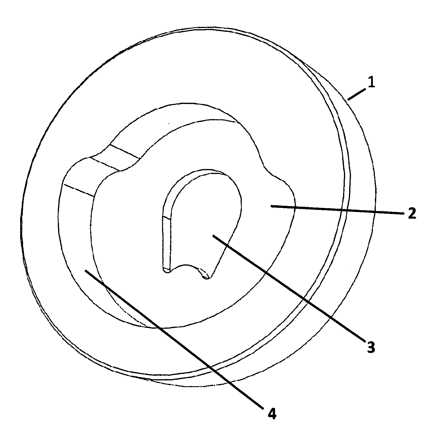
[0029]FIG. 3 shows a perspective sectioned view of the claimed embodiment (1), with recoil spring trapping recess (2), and bushing opening. (3)
[0030]FIG. 4 shows a side view of the end of the pistol slide (7), including the barrel bushing (5) and the spring plug (6).
[0031]FIG. 5 is a side view of the 1911 style pistol (8).
Operation:
[0032]After insuring the pistol (8) has been unloaded, the operator grasps the slide (7) firmly encircling the end of the slide with...
PUM
Abstract
A handgun bushing removal tool, designed to encompass the end of the slide, to facilitate the safe and rapid removal and replacement of the barrel bushing on a 1911 type semi-automatic pistol. The tool contains an aperture generally conforming to the shape of a 1911 barrel bushing, which the bushing passes through, which when held in the palm of the hand, allows direct pressure to be applied to the spring plug while the tool is rotated. The tool is also designed to limit the rotation of the bushing by contacting the slide wall with the end of the slide when the correct amount of rotation has been achieved.
Description
CROSS-REFERENCE TO RELATED APPLICATION[0001]This application claims the benefit of provisional patent application Ser. No. 61 / 461,838, filed 2011 Jan. 24 by the present inventor.BACKGROUNDPrior Art[0002]The following is a tabulation of some prior art that presently appears relevant:U.S. PatentsPat. No.Kind CodeIssue DatePatentee7,240,450B22007-07-10ShoberD103579S1937-03-16McNaught3,519,046B11970-07-07Pierce7,703,232B12010-04-27Johns4,901,411B11990-02-20Chestnut et alD407,958S1999-04-13Royse7,401,432B12008-07-22Perry4,037,275B11977-07-26Schor6,430,862B12002-08-13Berlin4,483,060B11984-11-20Farrar et al4,878,306B11989-11-07Dyer5,261,136B11993-11-16Hall6,032,398B12000-03-07Carpenter et alD564316S2008-03-18ElkaimD548552S2007-08-14ElkaimD540631S2007-04-17BryantD417372S1999-12-07CachotU.S. Patent Application PublicationsPublication Nr.Kind CodeIssue DateApplicant2005 / 0071925A12005-04-7Smith2005 / 0115399A12005-06-2VaidForeign Patent DocumentsApp orForeign Doc. Nr.Cntry CodeKind CodePub. Dt.P...
Claims
Application Information
Patent Timeline
Application Date:The date an application was filed.
Publication Date:The date a patent or application was officially published.
First Publication Date:The earliest publication date of a patent with the same application number.
Issue Date:Publication date of the patent grant document.
PCT Entry Date:The Entry date of PCT National Phase.
Estimated Expiry Date:The statutory expiry date of a patent right according to the Patent Law, and it is the longest term of protection that the patent right can achieve without the termination of the patent right due to other reasons(Term extension factor has been taken into account ).
Invalid Date:Actual expiry date is based on effective date or publication date of legal transaction data of invalid patent.

