

Steering Device
- Summary
- Abstract
- Description
- Claims
- Application Information
AI Technical Summary
Benefits of technology
Problems solved by technology
Method used
Image

Examples
Embodiment Construction
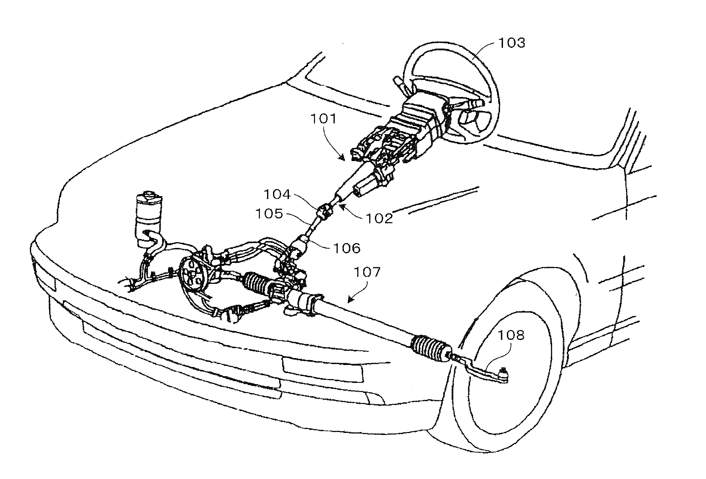
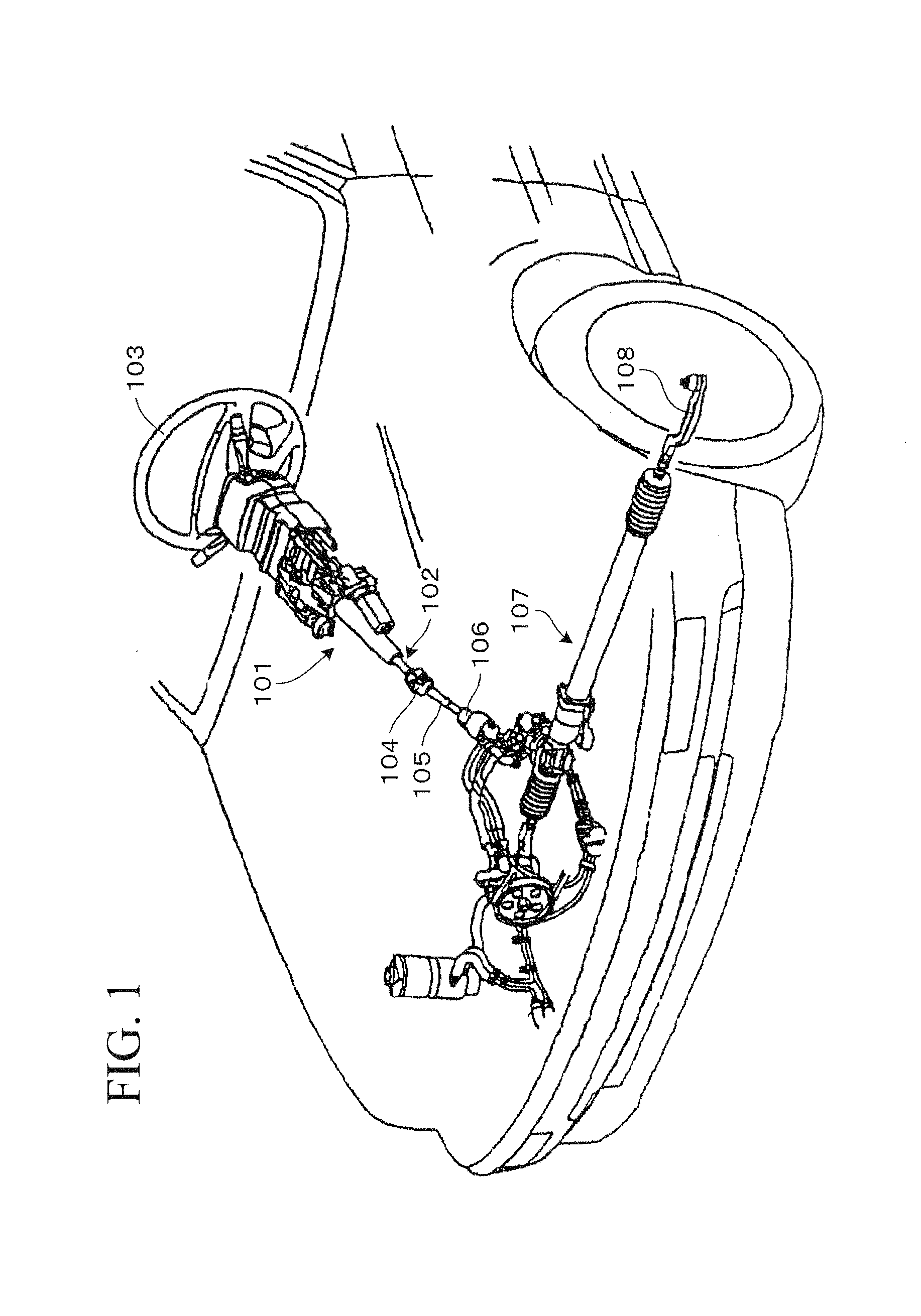
[0029]FIG. 1 is an overall perspective view of a steering device 101 installed in a vehicle according to an embodiment of the present invention. The steering device 101 axially rotatably supports a steering shaft 102. The steering shaft 102 is attached, at an upper end thereof (an end toward the vehicle rear), with a steering wheel 103 and connected, at a lower end thereof (an end toward the vehicle front), with an intermediate shaft 105 via a universal joint 104.
[0030]The intermediate shaft 105 is connected, at a lower end thereof, with a universal joint 106 which is connected with a steering gear 107 including a rack and pinion mechanism.
[0031]When a driver turns the steering wheel 103, the turning force is transmitted to the steering gear 107 via the steering shaft 102, universal joint 104, intermediate shaft 105, and the universal joint 106, thereby moving a tie rod 108 to change the steering angle of wheels.
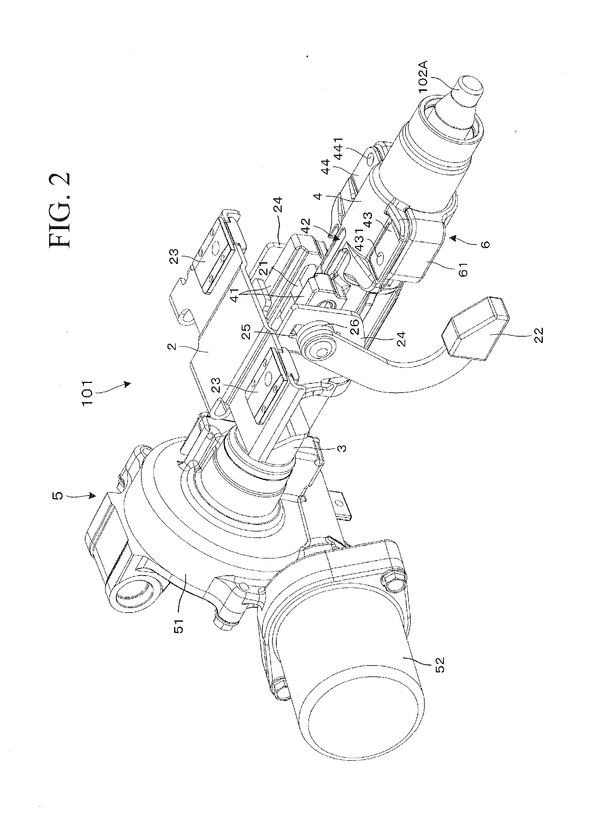
[0032]FIG. 2 is a perspective view, as seen from above on the left side...
PUM
 Abstract
Description
Claims
Application Information