
Wind power generation system and method

Inactive Publication Date: 2012-11-22
MEDIAN WIND
View PDF19 Cites 16 Cited by
  • Summary
  • Abstract
  • Description
  • Claims
  • Application Information

AI Technical Summary

Benefits of technology

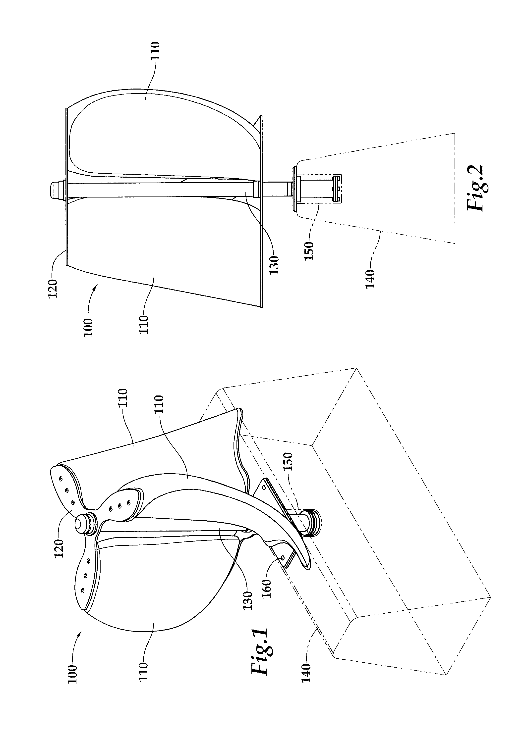
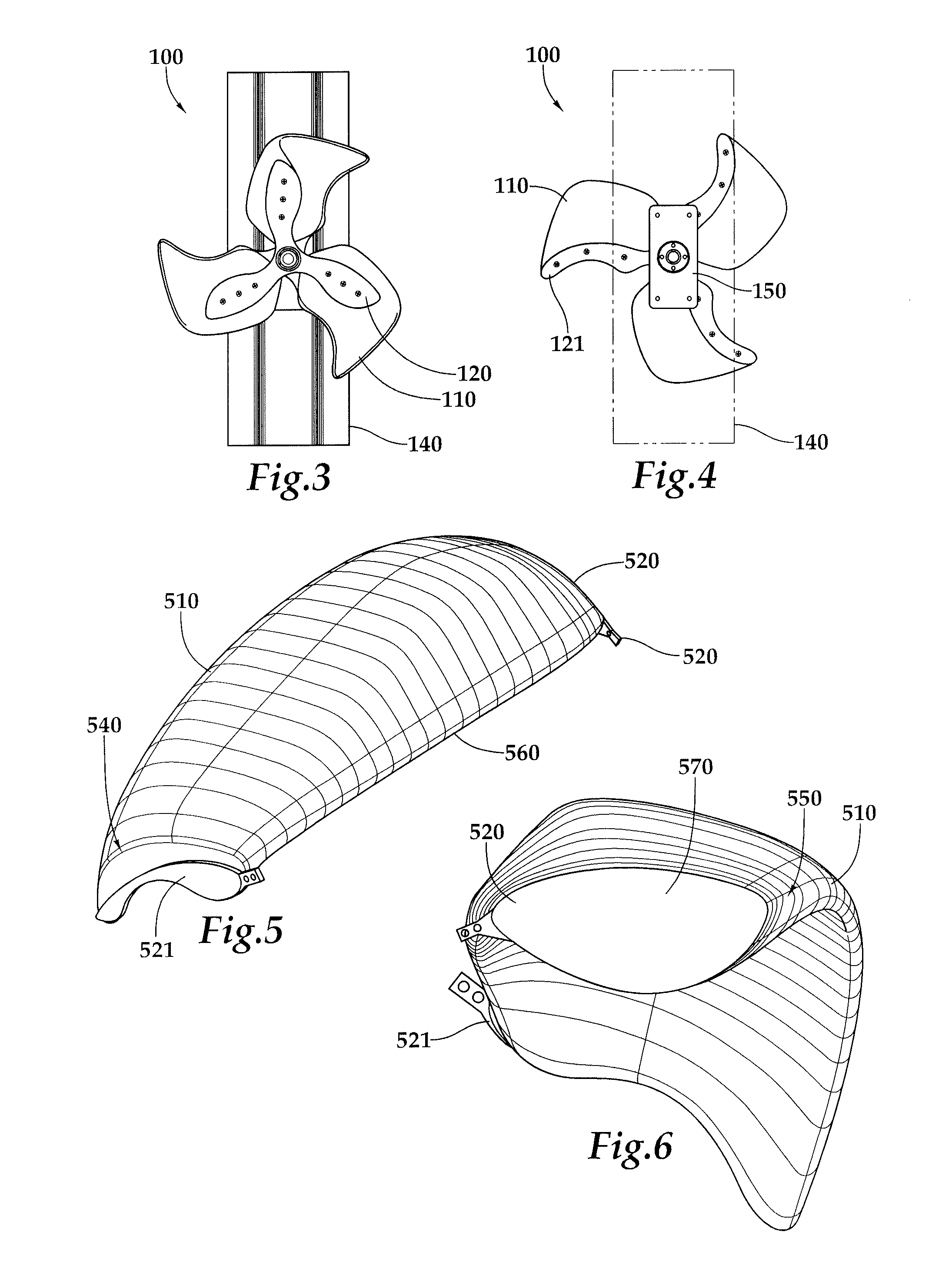
[0005]In another embodiment, a system for receiving wind and converting it to storable power, includes a wind capturing apparatus, including a least three sails, the least three sails having a shape, oriented to have an axis of rotation perpendicular to a surface on which the system is positioned, wherein the wind capturing device captures induced wind; an axle, in communication with wind capturing apparatus such that it receives rotational energy when the wind capturing apparatus rotates about the axis of rotation; and a generating unit, the generating unit receiving rotational energy from the axle and transforming it into storable energy. In one alternative, the shape is similar to a sail. In another alternative, the shape is an airfoil. In another alternative a lower camber of the airfoil is no more than zero. Alternatively, a lower camber of the airfoil is less than zero. Alternatively, the angle of attack is between 90 degrees to 45 degrees in relation to the surface on which the system is positioned. Optionally, an angle of attack is closer to 45 degrees at an edge of a leading edge further f

Problems solved by technology

Unfortunately, it is limited to remote areas of the country that have very strong winds.
Typically, wind power generators are extremely large and not easily deployed in a wide area.
Another problem with wind power is that the strength of area winds are not entirely predictable and there can be long lulls in the production of wind power that can put high demand on other segments of the power system.
The lack of predictability of wind power and the inability to deploy it regardless of the geographical location makes some wind power solutions less than optimal.

Method used


Image

  • Wind power generation system and method
  • Wind power generation system and method
  • Wind power generation system and method

Examples


Embodiment Construction

[0028]1) System for Generating Wind Power

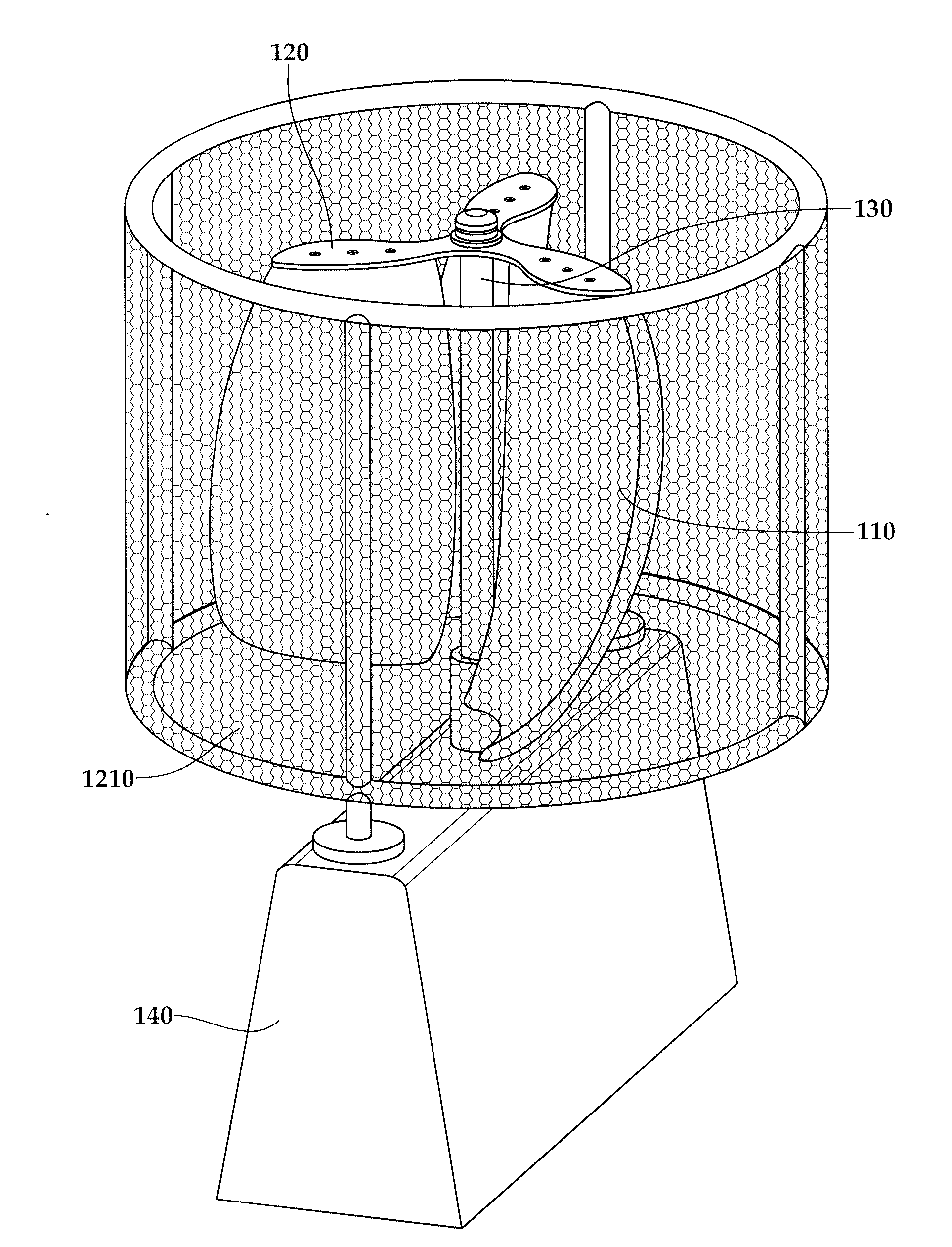
[0029]One embodiment of a system for generating wind power wind generator specifically designed to function atop roadway median barriers and atop barriers adjacent to roadways. While in alternatives, the angle of axis may be within a complete sphere or circle, in one embodiment a vertical axis shaft supports sails / blades which rotate around that axis. This axis, which is seated in bearings allowing for rotation, is captured at the base and captured at the top for support. The unique shape of a median barrier, which is designed to deflect vehicles back into their lane and direction of traffic, provides for a unique sail / blade design which best captures the forward moving and upward moving air displaced by vehicles. That shape is comprised of a sail which has curvature, as might be pictured in a traditional boat sail, thickness as in an airfoil, and a backward swept cupped shape as it reaches the top, not dissimilar from the curved palm of a ha...


PUM


Abstract

One embodiment of a system for receiving wind and converting it to storable power, includes a wind capturing apparatus, including a least three sails, the least three sails having a shape, oriented to have an axis of rotation perpendicular to a surface on which the system is positioned, wherein the wind capturing device captures induced wind; an axle, in communication with wind capturing apparatus such that it receives rotational energy when the wind capturing apparatus rotates about the axis of rotation; and a generating unit, the generating unit receiving rotational energy from the axle and transforming it into storable energy.

Description

CROSS-REFERENCE TO RELATED APPLICATIONS[0001]This application is a national stage application of PCT / US09 / 64626, filed on Nov. 16, 2009, which claims the benefit of U.S. Provisional Application No. 61 / 114,992, filed Nov. 14, 2008, both of which are incorporated by reference in their entirety.BACKGROUND[0002]Wind power has become a viable source of clean and renewable energy, and it is growing at 30% per year. Unfortunately, it is limited to remote areas of the country that have very strong winds. Typically, wind power generators are extremely large and not easily deployed in a wide area.[0003]Another problem with wind power is that the strength of area winds are not entirely predictable and there can be long lulls in the production of wind power that can put high demand on other segments of the power system. The lack of predictability of wind power and the inability to deploy it regardless of the geographical location makes some wind power solutions less than optimal.SUMMARY OF THE ...

Claims


Application Information

Patent Timeline
IPC IPC(8): F03D9/02
CPCF03D11/04F03D3/065F05B2240/14Y02E10/728F05B2250/25Y02B10/30Y02E10/74F05B2240/9113F03D13/20F03D9/25F03D3/062F03D9/255F03D9/46F03D80/70F03D80/00F03D3/005H02K7/183
Inventor HASKELL, ROGER L.
Owner MEDIAN WIND
Learn More