Magnetic beads for reducing leukocyte interference in immunoassays

a technology of immunoassays and magnetic beads, which is applied in the field of magnetic beads for reducing leukocyte interference in immunoassays, can solve the problems of increasing the cost of analysis of laboratory testing, affecting the patient's condition or prognosis, and reducing the effect of leukocyte interferen

Active Publication Date: 2012-11-22
ABBOTT POINT CARE
View PDF4 Cites 7 Cited by
  • Summary
  • Abstract
  • Description
  • Claims
  • Application Information

AI Technical Summary

Benefits of technology

[0016]The invention is directed to reducing or eliminating leukocyte interference in an analyte immunoassay as well as to kits, devices and methods for using such kits and devices.

Problems solved by technology

Laboratory testing increases the cost of analysis and delays the patient's receipt of the results.
In many circumstances, this delay can be detrimental to the patient's condition or prognosis, such as for example the analysis of markers indicating myocardial infarction and heart failure.
It is well known in the art that immunoassays are susceptible to various forms of interferences.

Method used


Image

  • Magnetic beads for reducing leukocyte interference in immunoassays
  • Magnetic beads for reducing leukocyte interference in immunoassays
  • Magnetic beads for reducing leukocyte interference in immunoassays

Examples


example 1

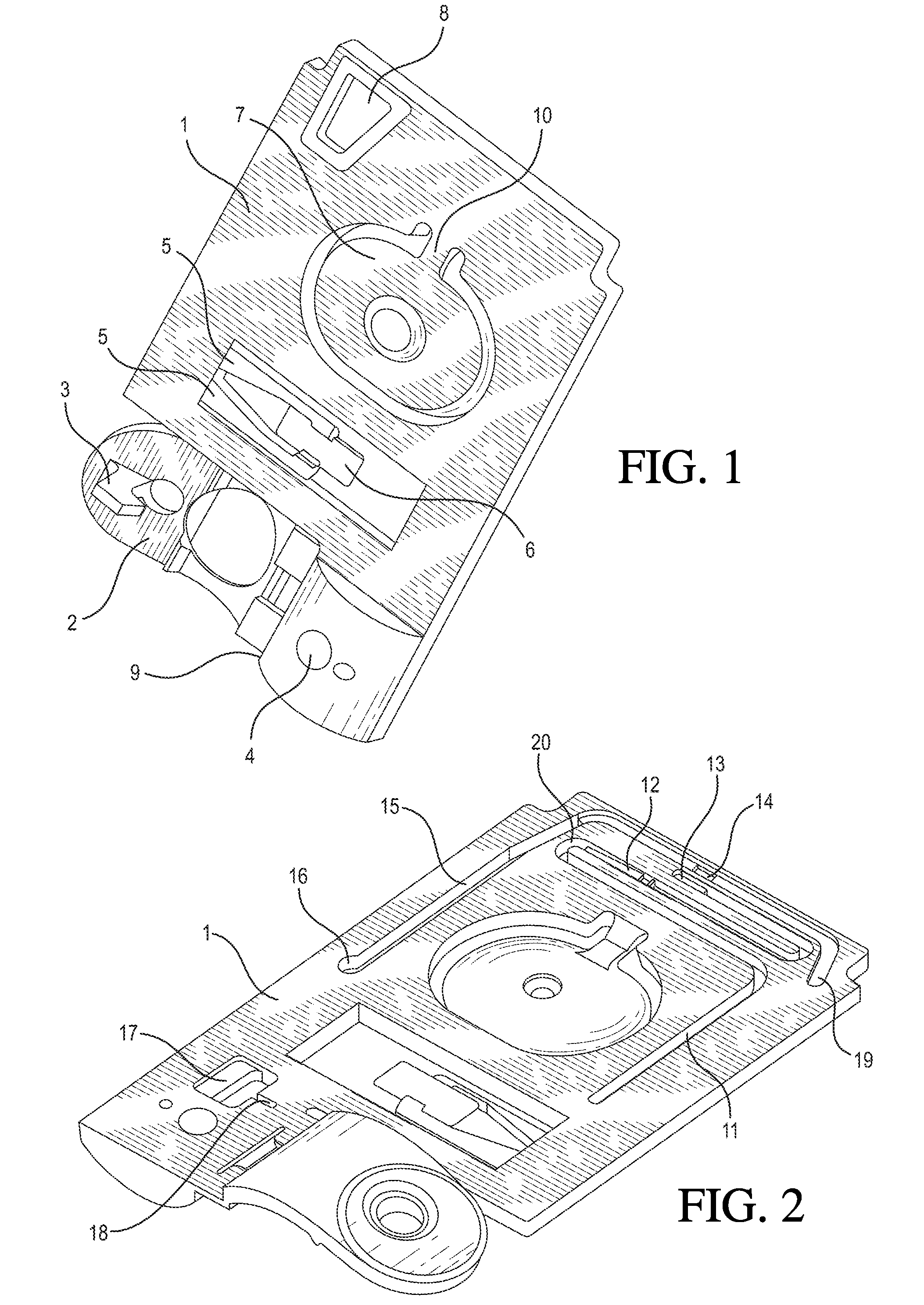
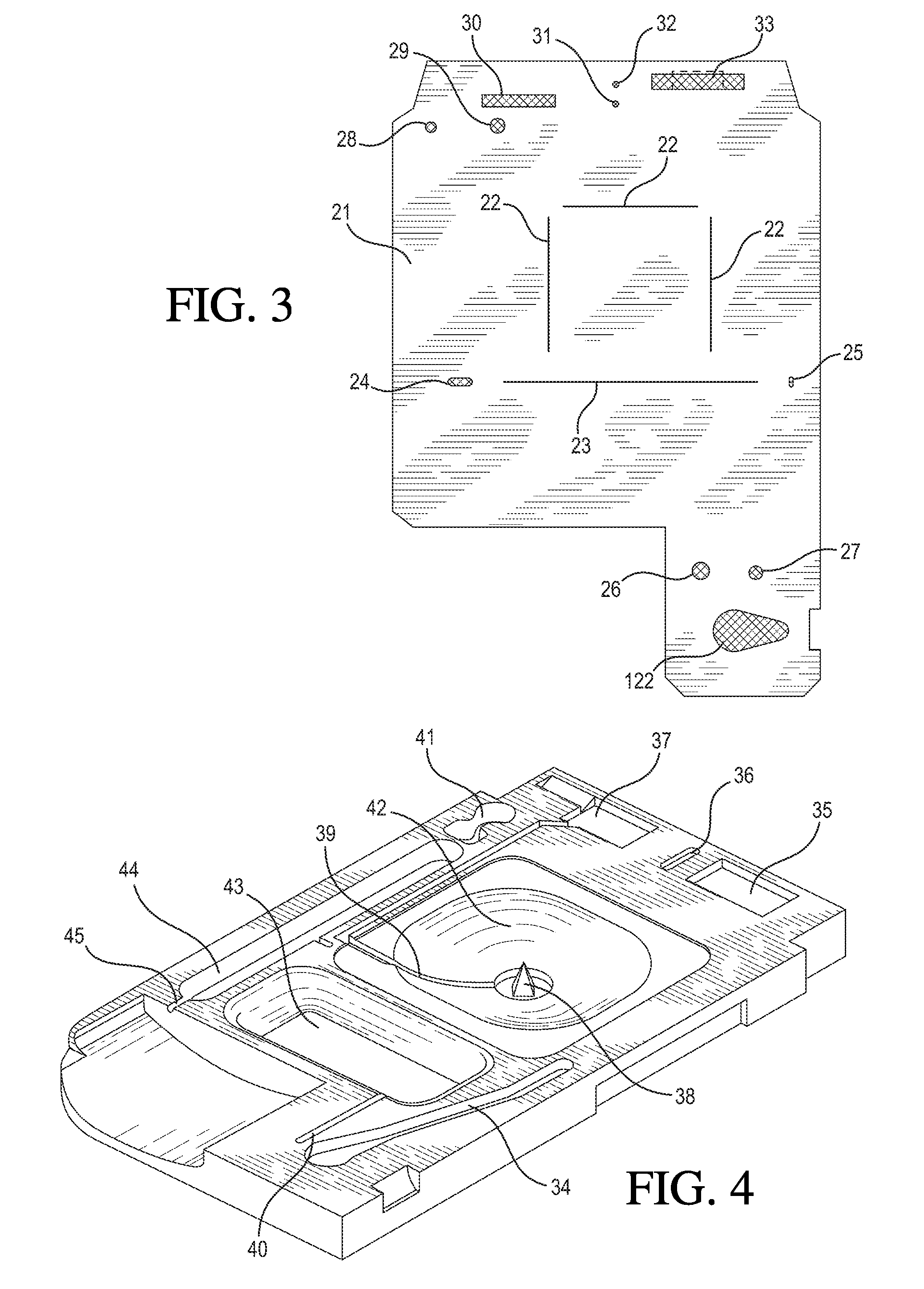
[0174]In one embodiment, an unmetered fluid sample is introduced into sample holding chamber 34 of a cartridge, through sample entry port 4. Capillary stop 25 prevents passage of the sample into conduit 15 at this stage, and holding chamber 34 is filled with the sample. Lid 2 or element 200 is closed to prevent leakage of the sample from the cartridge. The cartridge is then inserted into a reading apparatus, such as that disclosed in U.S. Pat. No. 5,821,399, which is hereby incorporated by reference. Insertion of the cartridge into a reading apparatus activates the mechanism, which punctures a fluid-containing package located at 42 when the package is pressed against spike 38. Fluid is thereby expelled into the second conduit, arriving in sequence at 39, 20, 12 and 11. The constriction at 12 prevents further movement of fluid because residual hydrostatic pressure is dissipated by the flow of fluid via second conduit portion 11 into the waste chamber 44. In a second step, operation o...

example 2

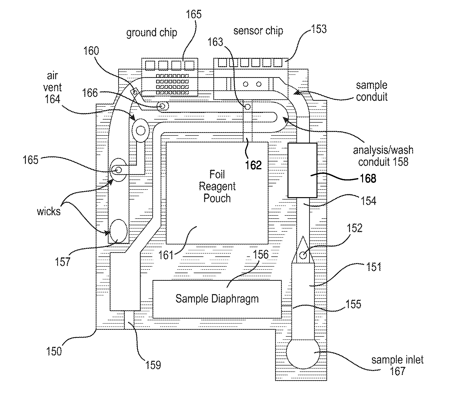
[0179]Referring now to FIG. 12, there is shown a top view of an immunosensor cartridge. Cartridge 150 comprises a base and a top portion, preferably constructed of a plastic. The two portions are connected by a thin, adhesive gasket or thin pliable film. As in previous embodiments, the assembled cartridge comprises a sample holding chamber 151 into which a sample containing an analyte of interest is introduced via a sample inlet 167. The sample is amended with opsonized magnetic sacrificial beads and a magnet 168 is used to retain the beads loaded with a target material (e.g., leukocytes) from the sample prior to delivery to the sensor chip 153. A metered portion of the sample is delivered to the sensor chip 153, via the sample conduit 154 (first conduit) as before by the combined action of a capillary stop 152, preferably formed by a 0.012 inch (0.3 mm) laser cut hole in the gasket or film that connects the two portions of the cartridge, and an entry point 155 located at a predeter...


PUM

PropertyMeasurementUnit
particle sizeaaaaaaaaaa

Abstract

Methods and devices for reducing interference from leukocytes in an analyte immunoassay are provided. In one embodiment, a method is provided comprising the steps of amending a biological sample with magnetic sacrificial beads opsonized to leukocytes, binding leukocytes in the sample to the magnetic sacrificial beads, and magnetically retaining the beads out of contact from an immunosensor.

Description

FIELD OF THE INVENTION[0001]The present invention relates to reducing or eliminating interference from buffy coat components, notably leukocytes, in devices and methods for determining the presence or concentration of an analyte in a blood sample by immunoassay. In particular, the invention relates to reducing or eliminating leukocyte immunosensor interference by amending a blood sample with opsonized magnetic sacrificial beads and similarly opsonized magnetic elements.BACKGROUND OF THE INVENTION[0002]A multitude of laboratory immunoassay tests for analytes of interest are performed on biological samples for diagnosis, screening, disease staging, forensic analysis, pregnancy testing and drug testing, among others. While a few qualitative tests, such as pregnancy tests, have been reduced to simple kits for a patient's home use, the majority of quantitative tests still require the expertise of trained technicians in a laboratory setting using sophisticated instruments. Laboratory test...

Claims


Application Information

Patent Timeline
Patent Type & Authority Applications(United States)
IPC IPC(8): G01N27/26
CPCY10T436/25125G01N33/54326
Inventor CAMPBELL, JOHN LEWIS EMERSONDAVIS, GRAHAM
Owner ABBOTT POINT CARE
Why Eureka
Try Eureka