Method and apparatus for determining a respiration signal

a technology of respiration signal and apparatus, applied in the field of method and apparatus for determining respiration signal, can solve the problems of sensor limitations, respiration band, degradation of measurement quality,

Active Publication Date: 2012-11-22
KONINKLIJKE PHILIPS ELECTRONICS NV
View PDF13 Cites 39 Cited by
  • Summary
  • Abstract
  • Description
  • Claims
  • Application Information

AI Technical Summary

Benefits of technology

[0008]It is an object of the present invention to provide a method and an apparatus which determine

Problems solved by technology

While continuous monitoring of the respiration signal, from which the respiration rate is extracted, is available on bedside monitors for intensive care patients, various portable sensor systems are being developed to allow unobtrusive and prolonged measurement and monitoring of the respiration signal of mobile patients in general wards with minimal discomfort.
In ambulatory patients, such as on the general ward or in home healthcare, these sensors have limitations.
A respiration band, for example, is considered to be too obtrusive by both medical personnel and patients.
Motion artifact is a well known issue in patient monitoring as a whole, which refers to the contamination of the physiolog

Method used


Image

  • Method and apparatus for determining a respiration signal
  • Method and apparatus for determining a respiration signal
  • Method and apparatus for determining a respiration signal

Examples


first embodiment

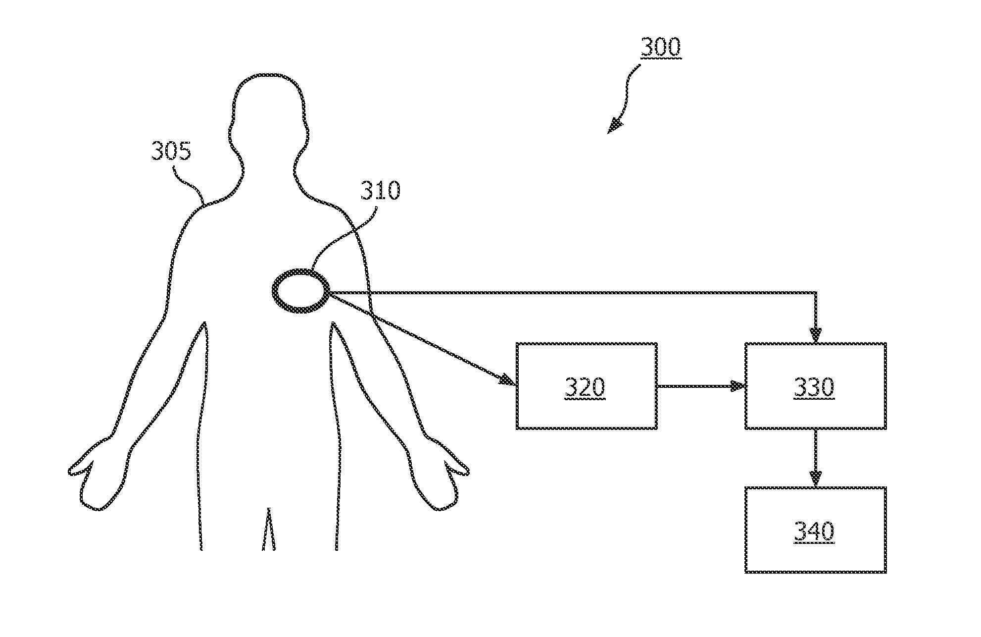
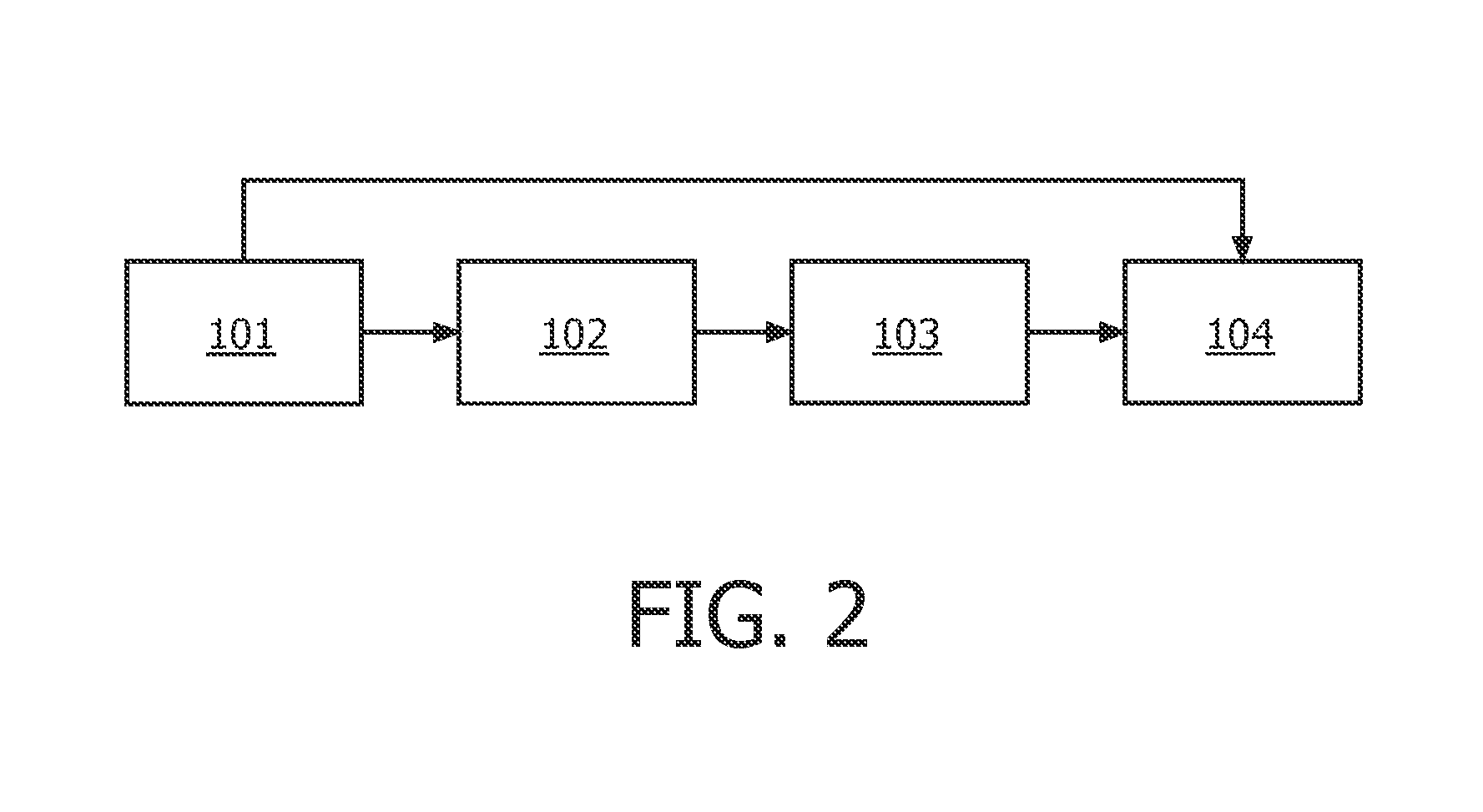
[0052]FIG. 2 shows schematically a method for determining the respiration of a person according to the invention. In step 101 three accelerometer signals are measured with one tri-axial accelerometer positioned at a suitable position on the body of a person, in this example on the thorax. The three measured accelerometer signals comprise information on the movement of the thorax due to respiration and due to non-respiratory movement or motion of the thorax, such as the heart beat, along three different axes, for example three orthogonal axes. The raw accelerometer signals measured in step 101 are used in step 102 in which the vector magnitude signal of the three raw accelerometer signals is calculated. The vector magnitude can for example be calculated by taking the vector sum of the three accelerometer signals representing the three different axes:

m(t)=√[x(t)2+y(t)2+z(t)2)]

where m(t) represents the vector magnitude of the accelerometer at time instant t, and x(t), y(t) and z(t) rep...

second embodiment

[0056]FIG. 5 illustrates schematically the method of determining the respiration of a person according to the invention. In step 101 three accelerometer signals are measured with one tri-axial accelerometer positioned at a suitable position on the body of a person, in this example the thorax. The three measured accelerometer signals comprise information of the movement of the thorax due to respiration and, in this example, due to movement of the person along three different axes, for example three orthogonal axes. The raw accelerometer signals measured in step 101 are used in step 102 in which the vector magnitude signal is calculated from the three raw accelerometer signals. The vector magnitude can for example be calculated by taking the vector sum of the three accelerometer signals representing the three different axes. In step 203 a characteristic frequency is extracted from the vector magnitude signal that was determined in step 102. Optionally, in step 203 first the vector mag...


PUM


Abstract

The invention relates to a method and apparatus for determining a respiration of a subject (305) in which, with a single multi-axial accelerometer (310) positioned on a body of the subject (305), accelerometer signals are generated (101) indicative of the acceleration of the subject (305) along different spatial axes, a vector magnitude signal of the acceleration of the subject (305) along the different spatial axes is calculated (102) from the accelerometer signals, a non-respiratory motion contribution to the acceleration along the different spatial axes is identified (103, 203) from the vector magnitude signal, which non-respiratory motion contribution is not caused by the respiration, and a respiration signal indicative of the respiration of the subject is determined (104, 204) by filtering the non-respiratory motion contribution from at least one of the accelerometer signals. In this way a method is provided which determines the respiration of a subject (305) with a single accelerometer (310) in an efficient and, for a patient, comfortable way.

Description

FIELD OF THE INVENTION[0001]The invention relates to a method and apparatus for determining a respiration signal.BACKGROUND OF THE INVENTION[0002]Respiration rate has proven to be a good indicator of the deterioration of the condition of a patient and it plays a crucial role in early warning hospital systems in combination with other vital body signs. Therefore, a need for continuous and reliable monitoring of a respiration signal is seen especially in the intensive care units of hospitals. A similar need, with less stringent requirements on the instantaneous presentation of the monitored parameters, is present in the general ward settings of hospitals and in home healthcare applications, such as in telemedicine and chronic disease management. While continuous monitoring of the respiration signal, from which the respiration rate is extracted, is available on bedside monitors for intensive care patients, various portable sensor systems are being developed to allow unobtrusive and pro...

Claims


Application Information

Patent Timeline
IPC IPC(8): A61B5/113A61B5/0205
CPCA61B5/113A61B2562/0219A61B5/721
Inventor MORREN, GEERT GUY GEORGES
Owner KONINKLIJKE PHILIPS ELECTRONICS NV
Why Eureka
Try Eureka