Surgical manipulation instrument

a surgical and instrument technology, applied in the field of surgical manipulation instruments, can solve the problems of affecting the accuracy of the monitor image, and limiting the freedom of movement of the surgical instrument, so as to achieve the effect of reducing the movement of the first actuation element, facilitating or facilitating the opening and closing of the screw connection, and facilitating coupling and decoupling

Active Publication Date: 2012-11-22
DEUTSCHES ZENTRUM FUER LUFT & RAUMFAHRT EV
View PDF1 Cites 28 Cited by
  • Summary
  • Abstract
  • Description
  • Claims
  • Application Information

AI Technical Summary

Benefits of technology

[0013]The first actuation elements are connected with the second actuation elements via a coupling device. The coupling device provides for a detachable connection of actuation element pairs. The coupling device comprises a first coupling element connected with the first actuation element. Further, the coupling device comprises a second coupling element that is connected with the second actuation element. Preferably, at least two actuation elements are provided which are connected through corresponding coupling devices so that a first and a second actuation element form a respective actuation element pair. According to the disclosure, a pivotable intermediate element is provided between the second coupling element and the second actuation element. Of course, a corresponding pivotable intermediate element may also be provided between the first coupling element and the first actuation element, the disclosure being hereinafter described with reference to a pivotable intermediate element provided between the second coupling element and the second actuation element. The pivotable intermediate element serves to translate an axial movement of the first actuation element into a pivot movement. The pivot movement of the intermediate element then causes an axial movement of the second actuation element. Depending on the design of the pivotable intermediate element it is possible, for instance, to realize an increase or decrease in the movement of the first actuation element. In particular, it is possible to decrease the movement of the first actuation element such that the second actuation element travels a shorter distance. This allows for a very precise handling.
[0020]According to another embodiment of a surgical manipulation instrument, in which the first and second actuation elements are moved in the axial direction, the connection is realized substantially by screwing a coupling element. Here, in a preferred embodiment, the fastening element pairs are designed such that one of the two fastening elements has a male thread and the other has a projection with a female thread. To avoid having to screw the individual fastening elements separately, a further preferred embodiment provides a ring that surrounds the fastening elements in the region of the coupling. A part of the fastening elements, preferably those with the internal toothing, is rotatably supported in the actuation element so that no turning of the actuation elements is necessary. Further, an elastic component is provided between the actuation elements, which compensates for manufacturing tolerances and allows a simultaneous screwing of all fastening elements. The ring has an inner toothing engaging toothings on the outer circumference of the fastening elements. Thus, rotating this ring causes the rotation of the individual actuation elements about their longitudinal axis. Thereby the actuation elements pairs are screwed together. If so desired, the ring may be driven by another ring, at least one gear being arranged between the two rings in a manner similar to a planet gear. Accordingly, the outer ring comprises an internal toothing, while the inner ring and the intermediate rings have an external toothing. Thereby, a transmission of the rotation and the force and thus a faster or easier opening and closing of the screw connection can be realized. This allows for a much faster coupling and decoupling of the actuation element pairs.

Problems solved by technology

The disadvantages of minimally invasive surgery include, among others, the limited freedom of movement of the surgical instruments.
Since the passage opening in the epidermis and the fat tissue can be seen as being a stationary opening forming an invariable point, this results in inverted movement ratios or an impeded hand-eye coordination with respect to the monitor image.
This may possibly be achieved by manual operation, however, this requires great aptness and long practice.
However, the actuators for driving the surgical manipulation instrument can generally not be autoclaved.
However, this play has adverse effects in the operation of the manipulation instrument or may even make an automatic control impossible.

Method used


Image

  • Surgical manipulation instrument
  • Surgical manipulation instrument
  • Surgical manipulation instrument

Examples


Embodiment Construction

with reference to preferred embodiments and to the accompanying drawings.

BRIEF DESCRIPTION OF THE DRAWINGS

[0022]In the Figures:

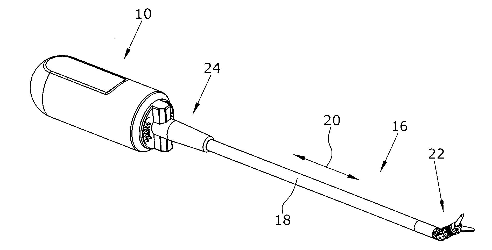
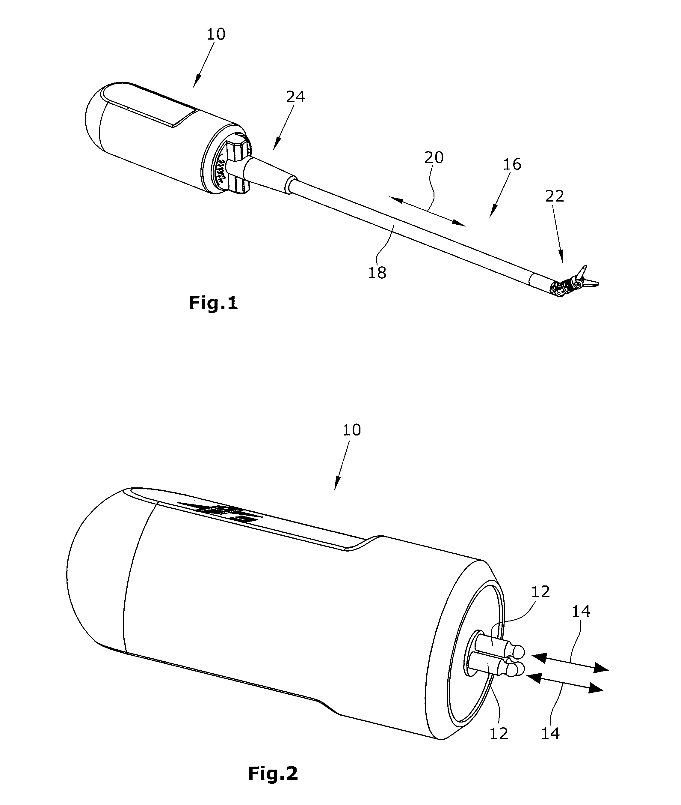
[0023]FIG. 1 is a schematic perspective view of a surgical manipulation instrument,

[0024]FIG. 2 is a schematic perspective side elevational view of the drive device,

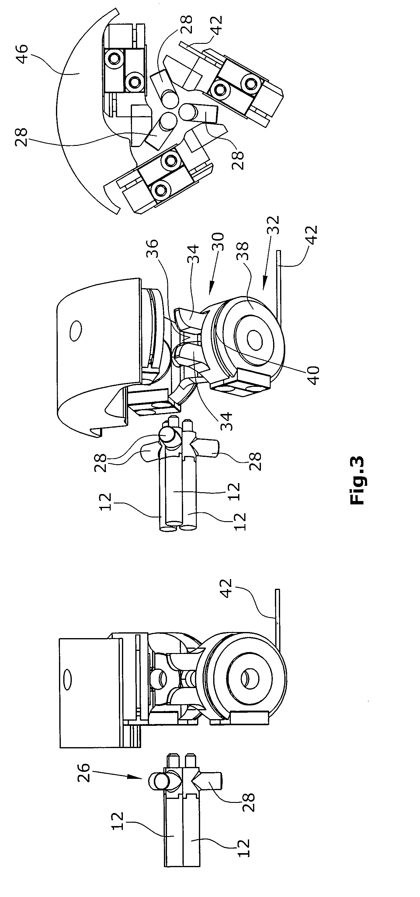
[0025]FIG. 3 are schematic illustrations of the first preferred embodiment of the disclosure, in which the actuation devices are not yet coupled with each other by means of the coupling device,

[0026]FIG. 4 are schematic illustrations of the first preferred embodiment of the disclosure, in which the actuation devices are coupled with each other by means of the coupling device,

[0027]FIG. 5 are schematic illustrations of a second preferred embodiment of the disclosure, in which the actuation devices are not yet coupled with each other by means of the coupling device,

[0028]FIG. 6 are schematic illustrations of the second preferred embodiment of the disclosure, in which the actuation devices are coupl...


PUM


Abstract

A surgical manipulation instrument which is particularly suitable for minimal invasive surgery, comprising an extra-corporeal drive device to which several axially displaceable first actuation elements are connected. The disclosure also relates to a partial intra-corporeal manipulator part which comprises several axially displaceable second actuation devices for actuating an end effector. Pairs of actuation elements are detachably connected together by means of a coupling device. A pivotable intermediate element is provided between the second coupling element and the second actuation element.

Description

BACKGROUND[0001]1. Field of the Disclosure[0002]The disclosure refers to a surgical manipulation instrument comprising a coupling detachably connecting an extra-corporeal drive portion and a partially intra-corporeal manipulator part.[0003]2. Discussion of the Background Art[0004]Surgical instruments that are not designed for single use, but for multiple use, have to be sterilized after each single use. Sterilizing can be performed using non-thermal or thermal methods. In everyday clinical practice, sterilizing is generally performed using thermal methods, in particular the so-called autoclaving. In autoclaving, the instrument to be sterilized is exposed for a certain time to water vapor under very high pressure which must wet all surfaces to be sterilized. In the autoclave, the instrument to be sterilized is exposed to temperatures up to 156° C. and pressures up to 2 bar for a period of up to 40 min. Autoclaving must be repeated after each use of the instrument so that in the cours...

Claims


Application Information

Patent Timeline
Patent Type & Authority Applications(United States)
IPC IPC(8): A61B19/00
CPCA61B19/22A61B2017/00477A61B2019/4868A61B2019/2242A61B34/70A61B34/71A61B2090/0813
Inventor SEIBOLD, ULRICHTHIELMANN, SOPHIESTROHMAYR, MICHAEL
Owner DEUTSCHES ZENTRUM FUER LUFT & RAUMFAHRT EV
Why Eureka
Try Eureka