Electromechanical lock

Active Publication Date: 2012-11-29
MG TECH CENT BV H O D N LOCK TECH
View PDF22 Cites 6 Cited by
  • Summary
  • Abstract
  • Description
  • Claims
  • Application Information

AI Technical Summary

Benefits of technology

[0009]The present invention addresses the foregoing problems by providing an electronic lock which has a simplified mechanical design regarding the interaction of the bolt and blocking member. In addition, the present design does not require the consumption of a great deal of energy and results in a power source that needs to be replaced infrequently.

Problems solved by technology

In known electronic locks, the interaction of the bolt and the blocking member is mechanically quite complex thus requiring complicated and expensive mounting.
In addition, most electronic locks require the consumption of a great deal of energy causing frequent replacement of the power source.
Thus, known electronic locks typically require the consumption of excess energy.

Method used


Image

  • Electromechanical lock
  • Electromechanical lock
  • Electromechanical lock

Examples


Embodiment Construction

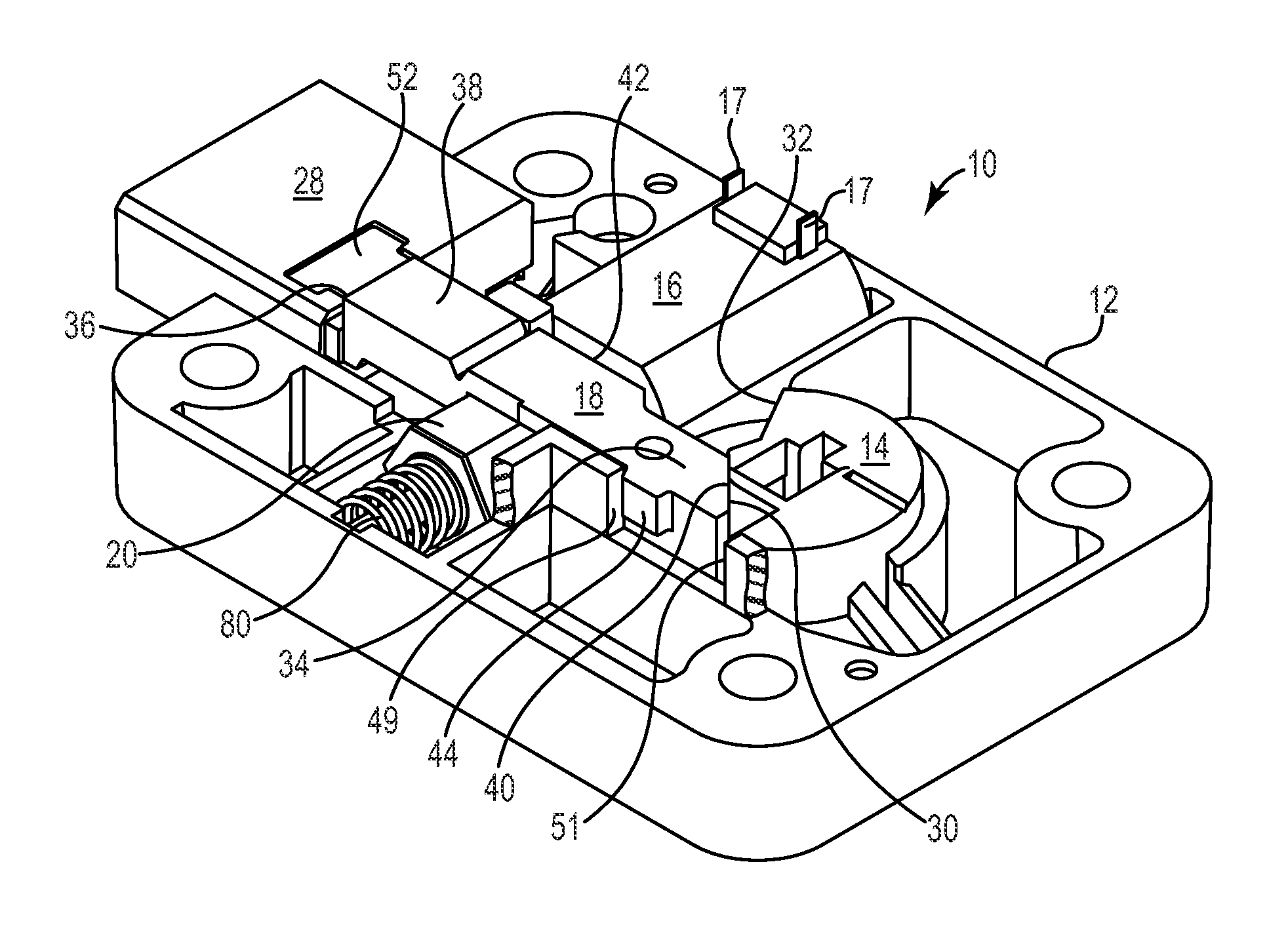
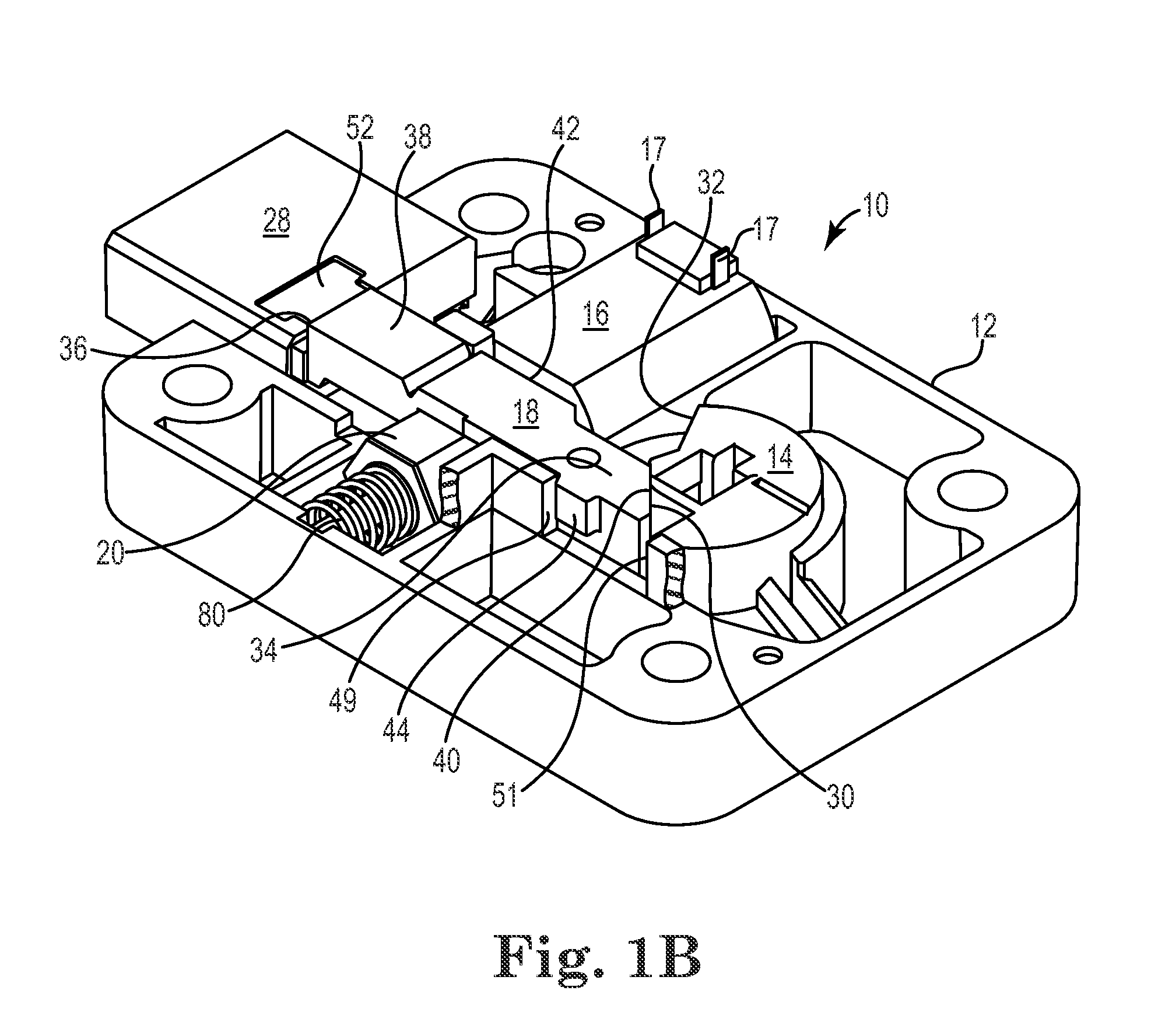
[0022]Referring now to FIGS. 1A and 1B, an exemplary embodiment of an electromechanical lock is depicted with FIG. 1B depicting the lock in the lock position. Electromechanical lock 10 broadly includes housing 12, cam 14, actuating device 16, locking lever 18, and blocking element 20. Locking lever 18 and blocking element 20 together comprise the locking mechanism 19 of the invention. Actuating device 16 may be a rotary motor or like alternatives known to those of ordinary skill in the art. Housing 12 is mounted to wall 22. Wall 22 is representative of the door of a safe, container or secure room. Shaft 24 operably engages cam 14 and extends through wall 22 where it mates with electronic dial 26. When a combination is input into electronic dial 26 a signal is transmitted to a circuit board located within the housing which recognizes the combination as correct or incorrect. If the combination is the correct combination, a signal is sent to actuating device 16 via contact points 17, w...


PUM


Abstract

An electromechanical lock comprises a housing, a rectilinear locking lever slidable within the housing, a blocking element positioned adjacent the locking lever that is movable between a first position that engages with the locking lever and a second position that disengages with the locking lever, and an actuating device operable to control movement of the blocking element between the first and second positions.

Description

BACKGROUND OF THE INVENTION[0001]1. Field of the Invention[0002]This invention relates to an improved electronic lock for securing goods and areas requiring a high degree of security. More particularly, this invention relates to an electronic lock that can be locked and unlocked electronically.[0003]2. Description of the Related Art[0004]Safes and other secure containers have traditionally used combination locks for controlling and authorizing entry. Conventional locks were mechanical and relied on a person dialing a correct combination on a rotating dial. The rotation positioned mechanical elements within the lock such that dialing the correct combination allowed a locking bolt to release the container door. Proper dial rotation aligned gates in tumblers. Once the gates were aligned, a fence on a fence lever entered the aligned gates. Continued rotation of the dial and tumblers pulled the fence lever and withdrew the bolt.[0005]However, over the years electromechanical locks have g...

Claims


Application Information

Patent Timeline
IPC IPC(8): E05B49/02E05B15/00
CPCE05B47/0012E05B47/0603E05B63/0017E05B2047/0069E05B83/02G07C9/00674E05B65/0075Y10T70/5212Y10T70/5319Y10T70/5336Y10T70/70Y10T70/7051Y10T70/7068Y10T70/7085Y10T70/7113Y10T70/7119Y10T70/7124Y10T70/713
Inventor GARTNER, KLAUS W.
Owner MG TECH CENT BV H O D N LOCK TECH
Why Eureka
Try Eureka