Security Device and System

a technology of security device and security system, which is applied in the field of security devices, can solve the problems of unfavorable onlookers, unfavorable onlookers, and unfavorable onlookers, and dramatically affect the overall cost of fence preparation, maintenance and replacement, so as to reduce the overall cost of installation and maintenance, the cost of the system described above can be easily appreciated, and the effect of shortening the set up tim

Active Publication Date: 2012-11-29
GALLAGHER ELECTRONICS LTD CO
View PDF6 Cites 11 Cited by
  • Summary
  • Abstract
  • Description
  • Claims
  • Application Information

AI Technical Summary

Benefits of technology

[0025]A major advantage of the present invention is that the shorter set up time significantly reduces overall cost in installation, and also maintenance. This is because the conductive link and length of material (e.g. wire) may be positioned and strained, respectively, in the same operation due the interaction between the tensioning device and the conductive component in the strainer.
[0026]With prior art systems, it can be necessary to spend considerable time in first straining the wire to a desired level, and then having to carry out the second task of positioning and fixing the conductive link at a different location to the strainer. A result of the new strainer is that set-up, repair and maintenance of the wire tensioning and the electrical connection can be performed as one step.
[0027]Because of the unique interaction between the conductive component and tensioning device in the present invention, the tension of the wire may be adjusted without substantial risk of affecting the electrical connection between two or more wires. In previous systems, readjustment of the electrical connection was often necessary after re-tensioning of wires, making such systems cumbersome and generally inconvenient.
[0028]It has been estimated that up to 75% of the installation costs of the systems (e.g. security fencing) are attributable to the technical process described above. The costs involved can be readily appreciated when considering that security fencing systems can often be installed over great distances of terrain (for example up to 100s of kilometres in length—e.g. border control). The present invention may help to significantly reduce the overall installation costs and maintenance, and ultimately have a dramatic effect on costs to a user implementing the strainer in security fence systems, and the like.
[0029]In currently available electric security fences, the insulative strainers are not used to transfer electric current from one strainer to another. Instead, a conductive link is separately positioned upstream of the strainer to transfer the current from one wire to an adjacent wire. In the current invention, the strainer is configured to allow passage of electric current using the integration of the conductive component and link between strainers while still allowing the body of the strainer to be made from an insulative material.
[0031]For example, it may help to avoid a perpetrator from breaching the security fence, especially without triggering an alarm. Previously, a perpetrator could cut the security wire upstream of the conductive link's position to avoid triggering an alarm. Movement of the conductive link to a peripheral position within the strainer may make it very difficult for this to occur.

Problems solved by technology

However, these systems above have a number of disadvantages as discussed below.
Installation of the conductive links and strainers requires considerable time, skill and effort to provide the desired outcome.
This dramatically affects the overall cost (due to man hours) in fence preparation, maintenance and replacement.
Furthermore, as the conductive link and strainer are separate units, the system described above can be untidy and unappealing to the onlooker.
This can be an issue for property holders that require security fences, yet want to maintain an aesthetic appearance to their fence and property.
Wires in fences are prone to loosening over time (due to stretching), and the strainers are often periodically used to re-tension the wires; usually rotation of the ratchet will achieve this result.
However, the conductive links located between the wires can become uneven due to wire adjustment which can add to the untidiness of the fence.
Fixing this unappealing feature requires further time, and ultimately cost.
Furthermore, as the conductive links are typically inflexible, the conductive links only have a certain amount of movement which will ultimately hinder the amount of possible adjustment of the wires.
Again, re-adjustment of the conductive links to address this problem can take further time and effort.
Currently available systems can also present a risk that a perpetrator can cut the security wire upstream of the conductive link's position to avoid triggering an alarm.

Method used


Image

  • Security Device and System
  • Security Device and System
  • Security Device and System

Examples


Embodiment Construction

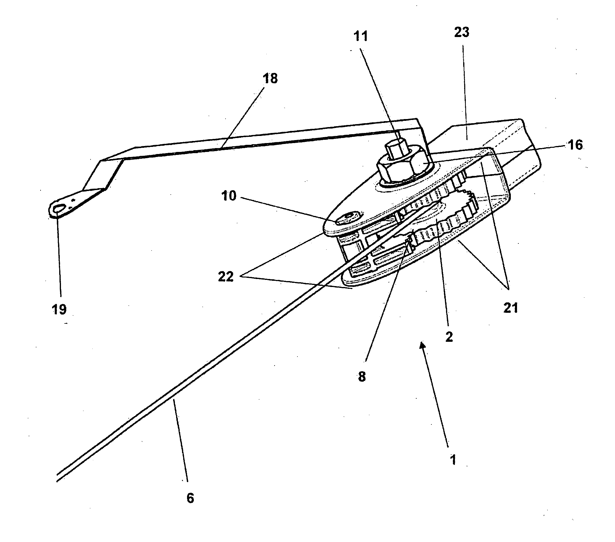
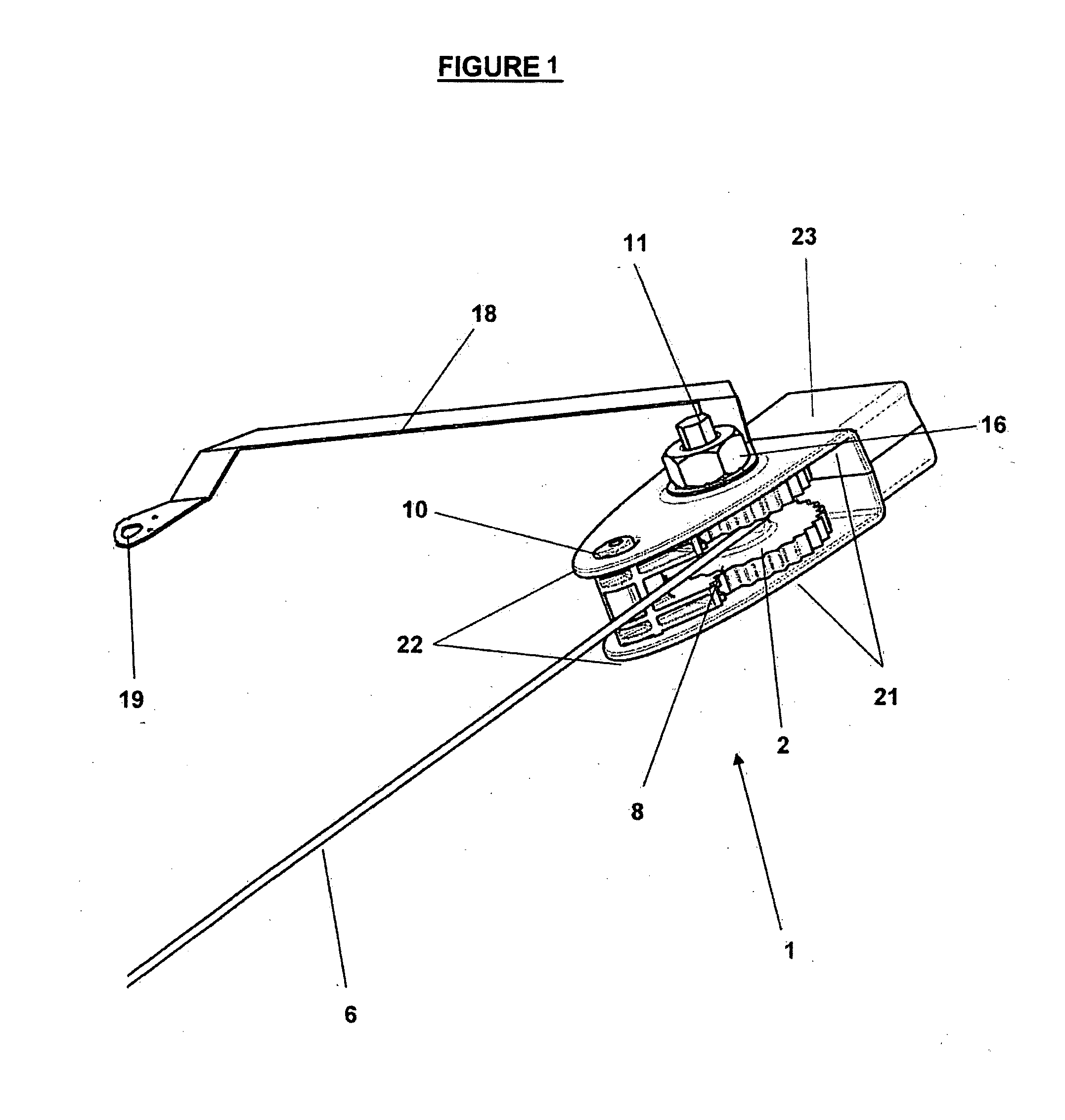
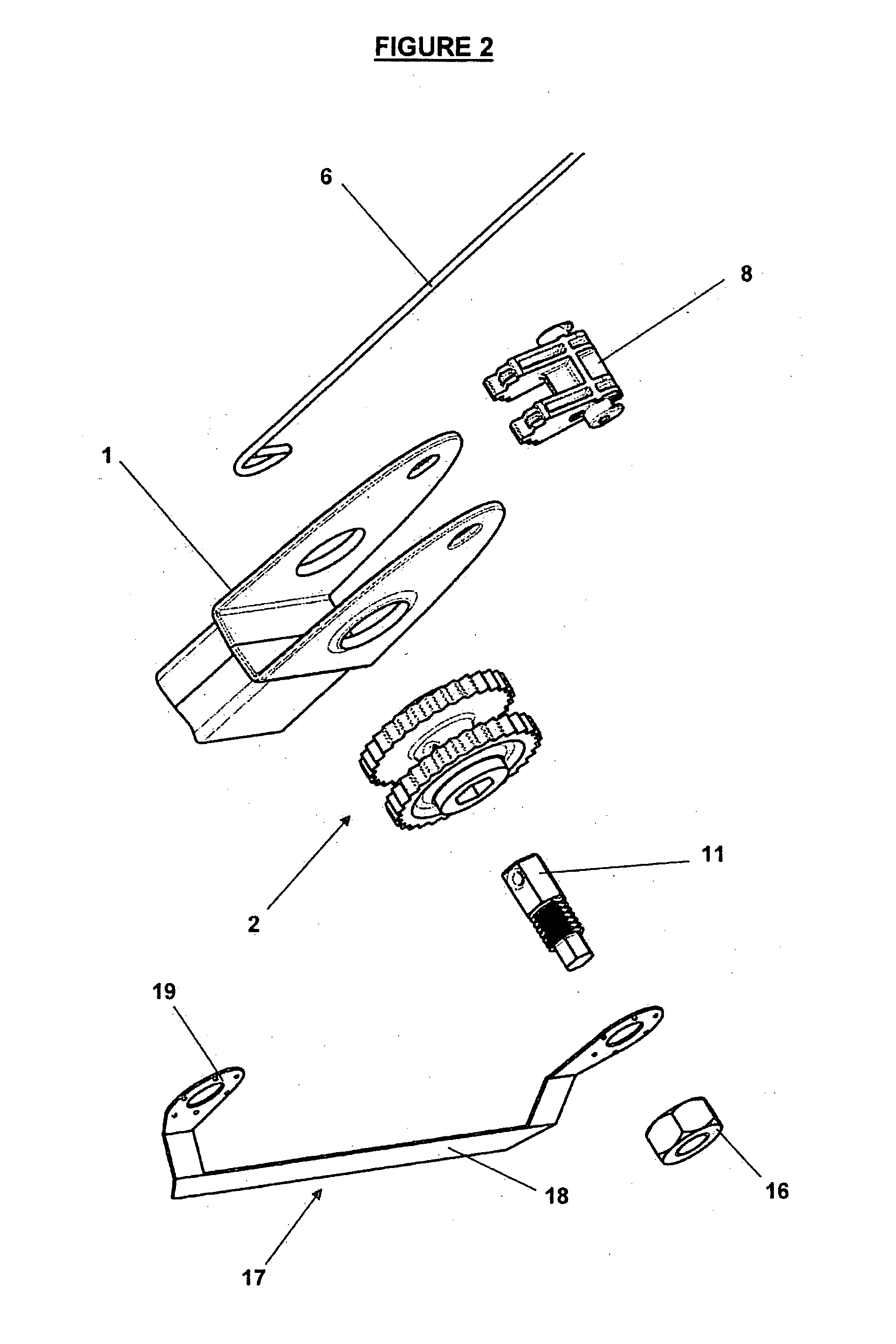
[0033]Throughout the specification, the term strainer should be taken as meaning any apparatus used for adjusting the tension of a length of material. Substantially any form of strainer may be used with the present invention. As such, alternatives or modifications not specifically discussed in this specification should not be considered beyond the scope of the invention.

[0034]A strainer which the Applicant considers appropriate for the present invention is discussed below to provide context. The tensioning device of the strainer may be retained within a housing.

[0035]The housing may include a backing portion which is configured to be attached to a fixed object, such as a wall or fence post. The housing may also include a head portion, which preferably retains the tensioning device.

[0036]The backing portion of the housing may be a box shape. Such a shape may allow sufficient surface area to fasten the backing portion to a support. For example, the backing portion may be fastened to a...


PUM

PropertyMeasurementUnit
lengthaaaaaaaaaa
lengthaaaaaaaaaa
conductiveaaaaaaaaaa

Abstract

A strainer for straining a length of material, the strainer including a tensioning device configured to tension a length of material between the strainer and an object, characterised in that the strainer includes a conductive component configured to contact the length of the material when held by the tensioning device, and wherein the conductive component includes an attachment portion for an external conductive link to the strainer. This invention also relates to a security system and its method of preparation using the strainer as described herein.

Description

TECHNICAL FIELD[0001]This invention relates to a security device and its method of use.BACKGROUND ART[0002]This invention will be discussed in relation to improvements in strainers used with wire in an electric security fence. However, a skilled person will appreciate that the principles of the present invention can be applied to tensioning lengths of other materials in different situations and is not necessarily limited to electric fences and / or wire.[0003]Strainers have been in use for numerous years to aid the tensioning of wire in fences, such as those used in the farming or security industries. The fences can be either conventional or electrified.[0004]Most current fence strainers utilise a ratchet pivotally attached to a strainer. The ratchet typically has a set of teeth around the circumference of the ratchet that interacts with a locking mechanism such as a pawl which is also attached to the main body of the strainer. The interaction between the teeth and the pawl allows the...

Claims


Application Information

Patent Timeline
Patent Type & Authority Applications(United States)
IPC IPC(8): B21F9/00H01R43/00E04H17/06
CPCA01K3/00Y10T29/49117E04H17/266A01K3/005E04H17/133
Inventor TYRRELL, KARENMALINS, CRAIG DAVIDSPENCER, RICHMOND BALCOMBE
Owner GALLAGHER ELECTRONICS LTD CO
Why Eureka
Try Eureka